Rockwell Automation Publication 1444-UM001D-EN-P - June 2018 55
Install the Dynamix 1444 Series Monitoring System Chapter 2
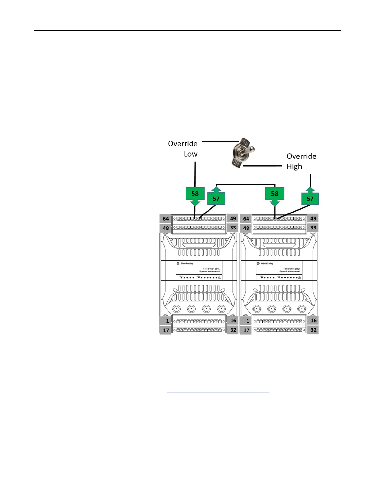
In applications where the buffered outputs are infrequently used, a switch can
be installed between pins 57 and 58. When installed, open the switch to enable
the buffered outputs, and close the switch to disable the outputs.
It is possible to use a common switch to manage the buffered outputs of
multiple modules as the override pins are opto-isolated from the module
circuitry. When a common switch is required, wire one contact to pin 57 of the
module nearest the switch and the other to pin 58 of each module to be
managed.
Figure 12 - Wiring Buffer Outputs Override
Consider the following with the module:
• When you connect pin 58 from multiple modules to pin 57 on one
module, allow for a maximum 3 mA current sink for each connected
override input.
•See Temperature Considerations
on page 30 for further information.
 Loading...