54 Rockwell Automation Publication 1444-UM001D-EN-P - June 2018
Chapter 2 Install the Dynamix 1444 Series Monitoring System
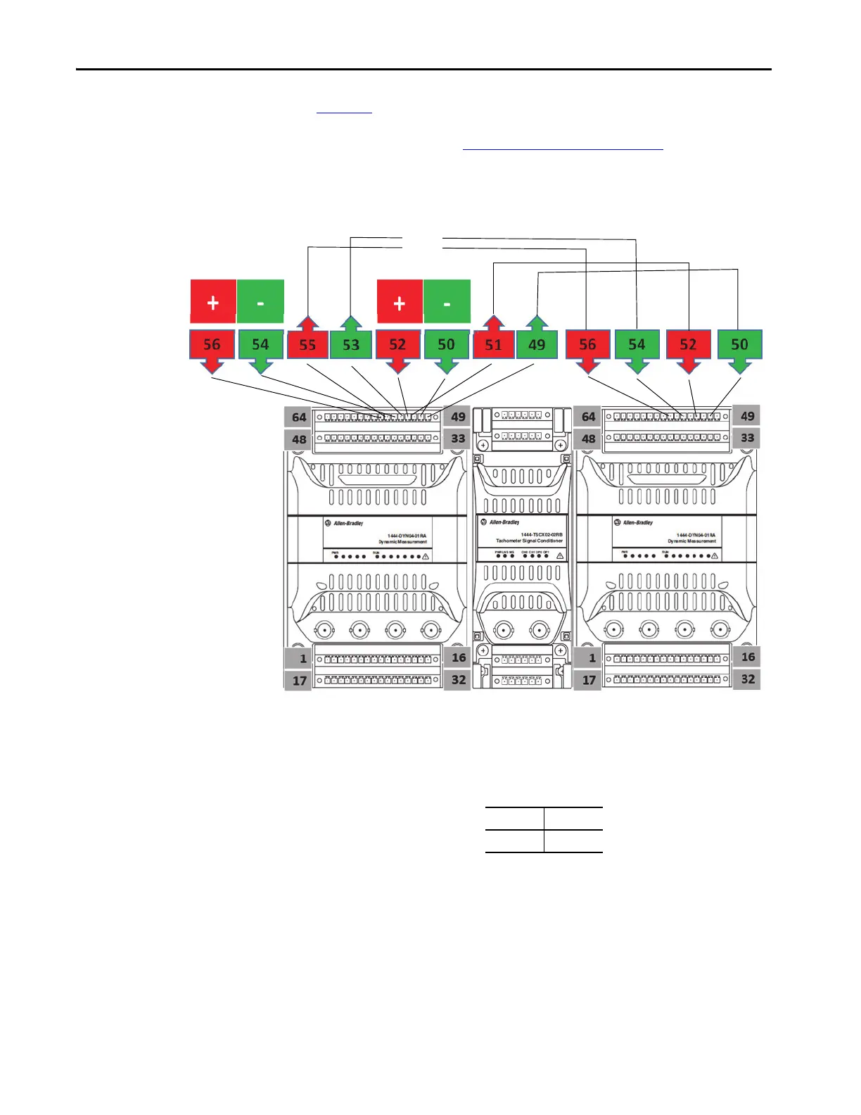
Figure 11 shows positive and negative power IN connections to the first of two
identical connectors for each, and power OUT from the second of two
identical connectors. See Upper Base Connector
on page 51 for the list of
power connections.
Figure 11 - Typical Wiring for Redundant Power Solutions to Multiple Modules
Buffered Output Override
The Buffered Output ‘Override’ connections, pins 57 and 58 on the 1444-TB-
A terminal base, are used to enable/disable the buffered outputs.
The buffered outputs are enabled (powered) when no connection is present
between pins 57 and 58.
The buffered outputs are disabled (not powered) when a connection is present
between pins 57 and 58.
Supply 0
24VDC
Power
Supply
Supply 1
24VDC
Power
Supply
58 57
OVR OVR
 Loading...