Rockwell Automation Publication 1444-UM001D-EN-P - June 2018 53
Install the Dynamix 1444 Series Monitoring System Chapter 2
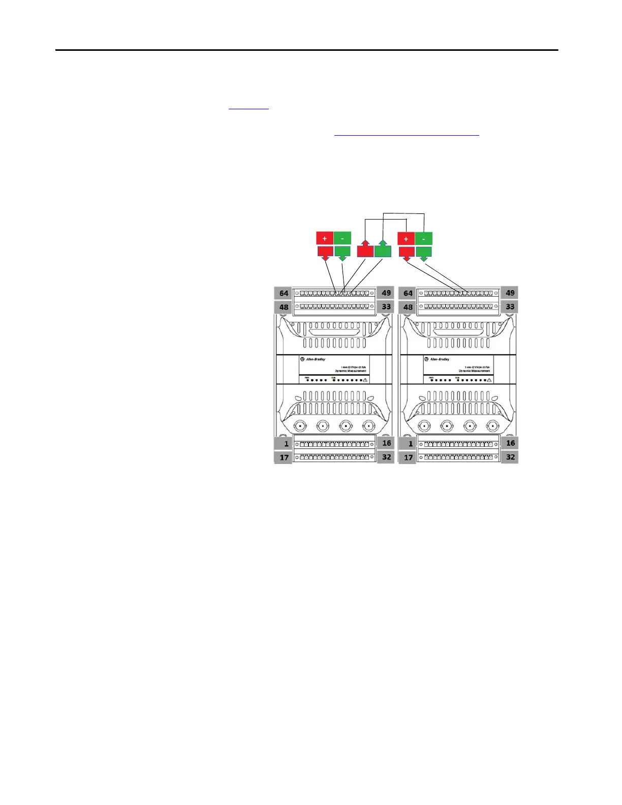
Wiring the Power to Multiple Modules
Figure 10 shows positive and negative power IN connected to the first of two
identical connectors for each, and power OUT from the second of two
identical connectors. See Upper Base Connector
on page 51 for the list of
power connections.
Figure 10 - Typical Wiring for Single Power Solutions to Multiple Module
Supply 0
24VDC
Power
Supply
56
54
55 53
56 54
 Loading...