Rockwell Automation Publication 1444-UM001D-EN-P - June 2018 61
Install the Dynamix 1444 Series Monitoring System Chapter 2
While the example shown in Figure 15 would provide a TTL class (0-5V)
signal, other voltage outputs can be achieved by applying an appropriate power
supply and resistor. Tab le 8
provides examples, one of which should suit most
common automation system inputs.
Table 8 - Power Supply and Resistor Examples
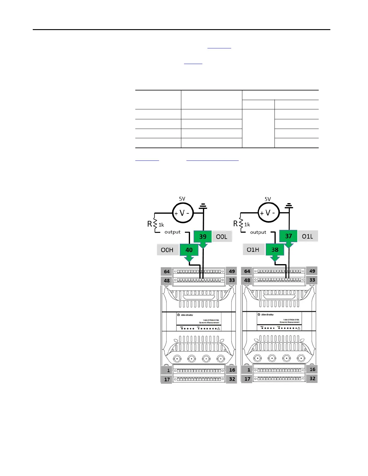
Figure 16, similar to Figure 15 on page 60, illustrates the specific pin
connections and circuit arrangement necessary for applying a typical ON/OFF
class circuit.
Figure 16 - Circuit Arrangement for Typical ON/OFF Class Circuit
Source Voltage Minimum Resister Value Typical Voltage When
Low High
32V DC 2.2K ohm ½ watt <0.5 32
24V DC 1.6k ohm ½ watt 24
12V DC 800 ohm ½ watt 12
5V DC 334 ohm ½ watt 5
 Loading...