Rockwell Automation Publication 1444-UM001D-EN-P - June 2018 87
Install the Dynamix 1444 Series Monitoring System Chapter 2
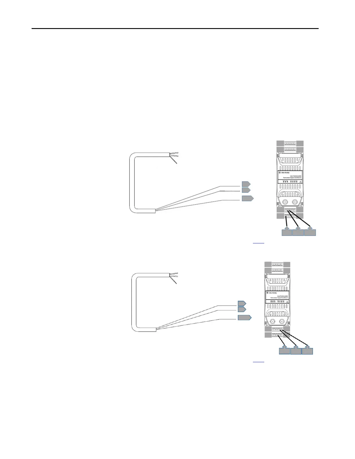
TTL Output Sensor
For any sensor or device that provides a TTL signal, such as a Hall Effect
sensor, the connected channel of the Tachometer Signal Conditioner must be
configured with:
• Transducer Type = TTL Signal, and
• Transducer Power = OFF
Wire the pickup as illustrated.
Figure 38 - Channel 0 Wiring for a TTL Signal
* Shield can be landed to any available shield connection. See the IMPORTANT note on page 56 for additional information.
Figure 39 - Channel 1 Wiring for a TTL Signal
* Shield can be landed to any available shield connection. See the IMPORTANT note on page 56 for additional information.
Shield Floating
Common
Signal
Shield
3
2
7*
24
19
18
13
1
6
712
7
23
Shield Floating
Common
Signal
Shield
6
5
10*
24 19
18
13
1
6
712
10
5
6
 Loading...