Rockwell Automation Publication MOTION-UM002E-EN-P - June 2016 49
Configure Kinematics Coordinate Systems Chapter 3
1. Determine and then configure the type of coordinate system you need
for your robot.
For help in determining your coordinate system type, see page 50
.
2. Establish the Joint-to-Cartesian reference frame relationship.
For more information regarding the joint-to-Cartesian reference frame,
see the section about the type of robot you are using.
3. Calibrate your robot (if applicable).
4. Identify your robot work envelope.
5. Determine and then configure the following parameters:
•Link lengths
• Base offsets
• End-effector offsets
6. Create the source and target coordinate systems.
7. Save the project.
8. Download the Kinematic project to the controller and then use the
MCT instruction to link the Joint coordinate system to the Cartesian
coordinate system.
The Joint-to-Cartesian reference frame relationship is automatically
established by the controller after the Joint coordinate system
ATTENTION: The correct relationship between the Joint reference frame and
the Cartesian reference frame must be established. Failure to do this can
allow your robot to move to unexpected positions causing machine damage
and/or injury or death to personnel.
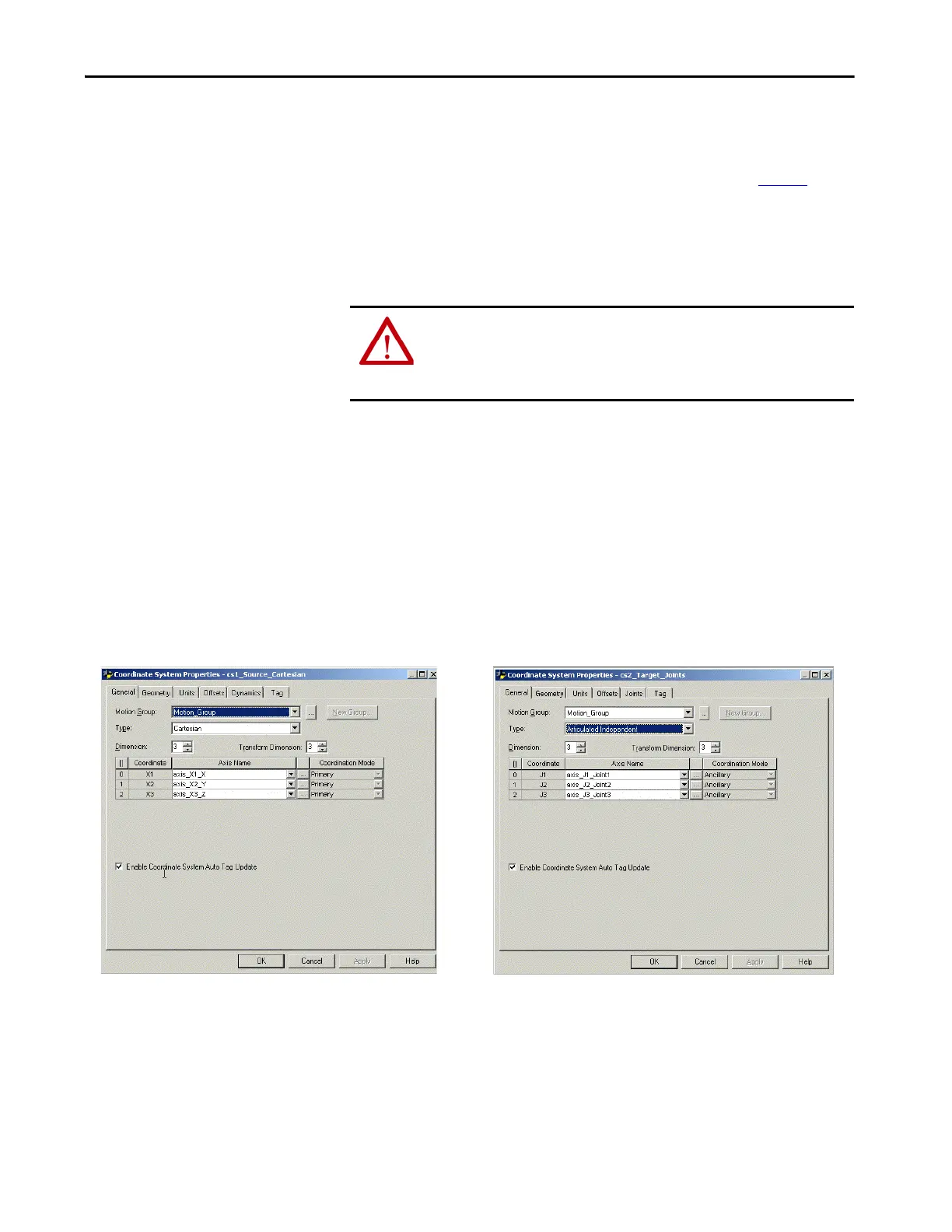
Typical Cartesian Coordinate System Configuration for Articulated Independent
robot.
Typical Joint Coordinate System Configuration for an Articulated Independent
robot.

 Loading...


