Publication 1794-6.5.8 - January 2010
80 Communication and I/O Image Table Mapping with the DeviceNet/ControlNet Adapter
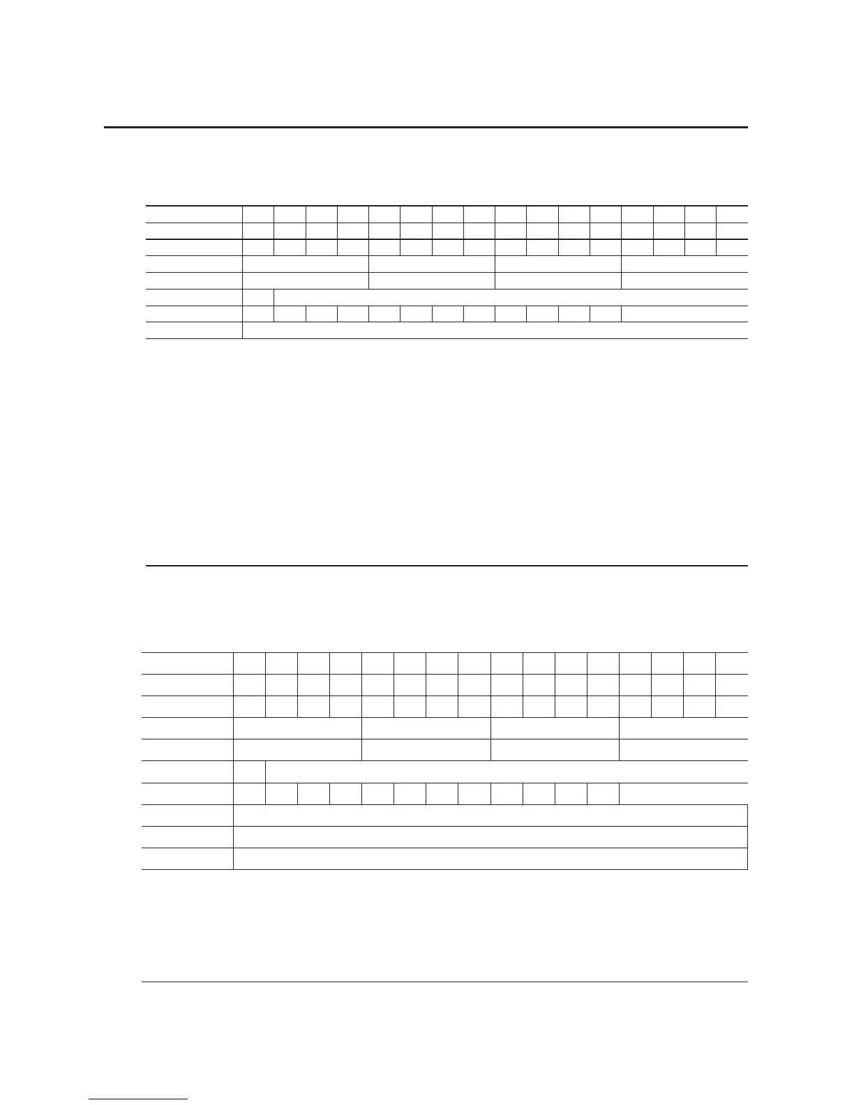
Table 5.2
Analog Input Module (1794-IF4ICFXT) Write
Dec. 15 14 13 12 11 10 9 8 7 6 5 4 3 2 1 0
Oct. 17 16 15 14 13 12 11 10 7 6 5 4 3 2 1 0
Word 0 EN000000000000000
Word 1 Channel 3 Filter Channel 2 Filter Channel 1 Filter Channel 0 Filter
Word 2 Ch 3 Configuration Ch 2 Configuration Ch 1 Configuration Ch 0 Configuration
Word 3 0 Real Time Sample Interval
Word 4 IC 1 TR IT 0 CH SK FS RV QK CK GO Channel Number
Word 5 Reserved
Where :
EN = Enable bit (not used on input module)
IC = Initiate Configuration bit
TR = Transparent bit
IT = Interrupt toggle bit
CH - Chop Mode Disable — use to disable the chop mode. Chop mode used by the module to reduce offset and drift errors. The
default is chop mode enabled (0).
SK = FIR Filter Disable — use to disable the FIR filter. The Finite Impulse Response filter is used by the module to improve signal
stability. The default is FIR filter enabled (0).
FS = Fast Step Response — use to enable a fast step response algorithm. The fast step response algorithm, upon sensing a step
input, uses an averaging method rather than the FIR filter. The FIR goes back into operation once the input has settled. The
default is fast step response disabled (0).
RV = Revert to default bit
QK = Quick calibration
CK = Calibration clock
GO = Gain Offset select
Table 5.3
Analog Input Module (1794-IF4I) Write Configuration Block
Word/Dec. Bit 15 14 13 12 11 10 09 08 07 06 05 04 03 02 01 00
Word/Octal Bit 17 16 15 14 13 12 11 10 07 06 05 04 03 02 01 00
Word 1 EN000000000000000
Word 2 Chnl 3 Filter Chnl 2 Filter Chnl 1 Filter Chnl 0 Filter
Word 3 Chnl 3 Configuration Chnl 2 Configuration Chnl 1 Configuration Chnl 0 Configuration
Word 4 0 Real Time Sample Programmed Interval
Word 5 IC 1 TR IT 0 0 0 0 RV QK CK GO Channel Number
Word 6 Not used
Word 7 Not used
Word 7 Not used
Where:
EN = Not used on the 1794-IF4I.
IC = Initiate configuration bit
TR = Transparent bit
IT = Interrupt Toggle bit
RV = Revert to defaults bit
QK = Quick calibration
CK = Calibration clock
GO = Gain offset select

 Loading...


