154 Rockwell Automation Publication 825-UM004D-EN-P - November 2012
Chapter 11 Testing & Troubleshooting
Delta-Connected Voltages
Perform the following steps to test delta-connected voltages:
1. Connect the current source to the MCM module, as shown in Fi
gure50
on page151.
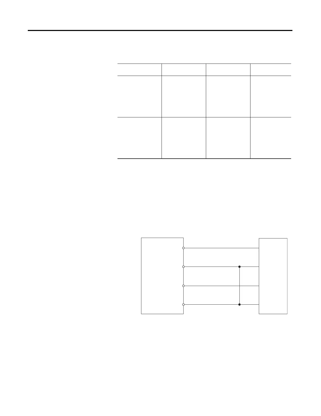
2. Connect the voltage source to the 825-P, as shown in Fig
ure 52. Make sure
that Xfmr Connection=Delta.
Figure 52 - Delta Voltage Source Connections
3. Use the front panel SET/SHOW or MPS Explorer software to record the
Phase CT Ratio, Phase VT Ratio, and Phase Rotation setting values.
4. A
pply the current and voltage quantities shown in Column 1 of Tab
le 88.
Values are given for Phase Rotation = ABC and Phase Rotation = ACB.
5. Use the front panel METER or MPS Explorer software to verify the
resu
lts.
Table 87 - Power Quantity Accuracy — Wye Voltages
Applied Currents and
Voltages
Real Power
(kW) Reactive Power (kVAR)
Power Factor
(pf)
PHROT = ABC
Ia = 2.5 ∠−26
Ib = 2.5 ∠−146
Ic = 2.5 ∠+94
Expected:
P =
0.4523 • CTR1 • PTR
Expected:
Q =
0.2211 • CTR1 • PTR
Expected:
pf =
0.90 lag
Va = 67 ∠0
Vb = 67 ∠−120
Vc = 67 ∠+120
Measured: Measured: Measured:
PHROT = ACB
Ia = 2.5 ∠−26
Ib = 2.5 ∠+94
Ic = 2.5 ∠−146
Expected:
P =
0.4523 • CTR1 • PTR
Expected:
Q =
0.2211 • CTR1 • PTR
Expected:
pf =
0.90 lag
Va = 67 ∠0
Vb = 67 ∠+120
Vc = 67 ∠−120
Measured: Measured: Measured:
825-P
L1
L2
L3
N
Voltage
Test
Source
VA
VB
VC
VN

 Loading...