Rockwell Automation Publication 825-UM004D-EN-P - November 2012 153
Testing & Troubleshooting Chapter 11
Power and Power Factor Measuring Accuracy
The following tests assume use of an MCM2, MCM5, or MCM20 converter
module.
Wye-Connected Voltages
Perform the following steps to test wye-connected voltages:
1. Connect the current source to the MCM module, as shown in Fig
ure 50.
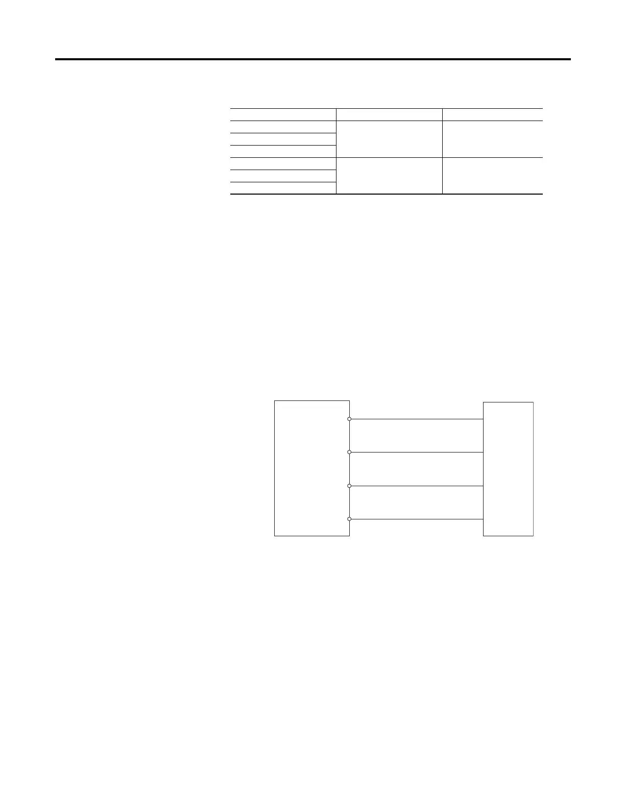
2. Connect the voltage source to the 825-P, as shown in Fig
ure 51. Make sure
that Xfmt Connection = Wye.
Figure 51 - Wye Voltage Source Connections
3. Using the front panel SET/SHOW or MPS Explorer software, record the
Phase CT Ratio, Phase VT Ratio, and Phase Rotation setting values.
4. Apply the current and voltage quantities shown in Column 1 of Ta b
le 87.
Values are given for Phase Rotation = ABC and Phase Rotation = ACB.
5. Use the front panel METER function or MPS Explorer software to verify
the
results.
|IA| = FLA 12%
|IB| = 1.2 • FLA
|IC| = 1.2 • FLA
|IA| = 0.9 • FLA 13%
|IB| = 1.1 • FLA
|IC| = 1.1 • FLA
Table 86 - Current Unbalance Measuring Accuracy
|I| Applied (A secondary) Expected Reading (%) Actual Reading (%)
825-P
L1
L2
L3
N
Voltage
Test
Source
VA
VB
VC
VN

 Loading...