114 Rockwell Automation Publication KNX-RM009C-EN-P - May 2019
Kinetix 5500 Drive Systems
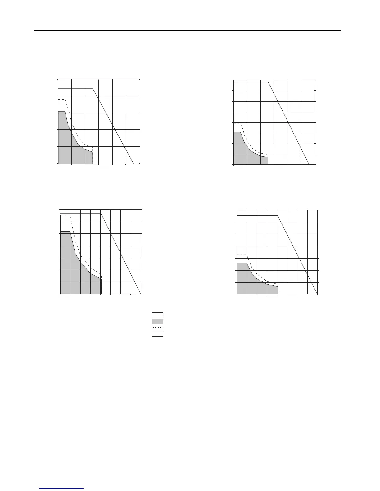
Kinetix 5500 Drives/MP-Series (ball screw) Electric Cylinder Curves (continued)
10,000
8000
6000
4000
2000
0
2248
1798
1349
899
450
0
Force
(N)
Force
(lb)
Velocity (mm/s)
50
200150
0
300
250
100
2198-H025-ERSx and MPAI-A4xxxCM3
2198-H015-ERSx and MPAI-B4xxxCM3
Force
(N)
Force
(lb)
8000
7000
6000
5000
4000
3000
2000
1000
0
1798
1573
1349
1124
899
674
450
225
0
Velocity (mm/s)
100
400300
0
600
500
200
2198-H025-ERSx and MPAI-A4xxxEM3
2198-H008-ERSx and MPAI-B4xxxEM3
Force
(N)
Force
(lb)
14,000
12,000
10,000
8000
6000
4000
2000
0
3147
2698
2248
1798
1349
900
450
0
Velocity (mm/s)
100
0
50
200
2198-H040-ERSx and MPAI-A5xxxCM3
2198-H015-ERSx and MPAI-B5xxxCM3
150
Force
(N)
Force
(lb)
14,000
12,000
10,000
8000
6000
4000
2000
0
3147
2698
2248
1798
1349
900
450
0
Velocity (mm/s)
200
0
100
400
2198-H040-ERSx and MPAI-A5xxxEM3
2198-H015-ERSx and MPAI-B5xxxEM3
300
= Continuous operating region @ 25 °C (77 °F)
= Continuous operating region @ 40 °C (104 °F)
= Intermittent operating region, 450 mm (18 in.) stroke length only
= Intermittent operating region, 076…300 mm (3…12 in.) stroke lengths

 Loading...


