142 Rockwell Automation Publication 2198-UM002G-EN-P - February 2019
Chapter 5 Connect the Kinetix 5700 Drive System
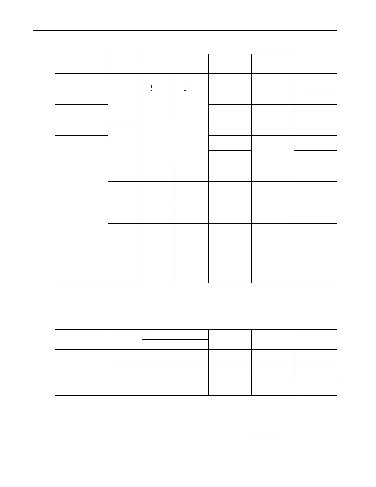
Table 66 - Regenerative Bus Supply Wiring Requirements
Table 67 - iTRAK Power Supply Wiring Requirements
Regen Bus Supply
Cat. No.
Description
Connects to Terminals
Wire Size
mm
2
(AWG)
Strip Length
mm (in.)
Torque Value
N•m (lb•in)
Pin Signal
2198-RP088
Mains input
power
6…10
(1)
(10…8)
10.0 (0.39)
0.5…0.8
(4.4…7.1)
2198-RP200
10…35
(8…2)
20.0 (0.79)
2.5…4.5
(22…40)
2198-RP263
2198-RP312
21.1…120
(4…250 kcmil)
27.0 (1.06)
15…20
(132…177)
2198-RP088
2198-RP200
PELV/SELV
24V power
(connector plug)
CP-1
CP-2
24V+
24V–
0.5…4
(20…12)
7.0 (0.28)
0.22…0.25
(1.9…2.2)
2198-RP263
2198-RP312
1.5…4
(16…12)
10.0 (0.39)
0.5…0.6
(4.4…5.3)
6 (10)
0.7…0.8
(6.1…7.0)
2198-RPxxx
DC Bus power Bus bar
DC–
DC+
N/A
(2)
N/A
(3)
N/A
(3)
Contactor enable
OK+
OK–
EN–
EN+
CONV OK+
CONV OK–
CONT EN–
CONT EN+
0.14…2.5
(26…12)
7.0 (0.28)
0.4…0.5
(3.5…4.4)
Active shunt
RC-2
RC-1
DC+
DC–
1.5…6
(16…10)
12.0 (0.47)
0.5…0.6
(4.5…5.3)
Digital inputs
IOD-1
IOD-2
IOD-3
IOD-4
IOD-5
IOD-6
IOD-7
IOD-8
IOD-9
IOD-10
IN1
COM
IN2
COM
SHLD
IN3
COM
IN4
COM
SHLD
0.14…1.5
(26…16)
10.0 (0.39) N/A
(3)
(1) Applies to solid wire. If using stranded wire, the maximum wire size is 6 mm
2
(10 AWG). To meet CE requirements above 40 °C (104 °F) for 6 mm
2
stranded wires, single-core copper
conductors must be used with 90 °C minimum rating.
(2) Shared DC-bus power connections are always made from drive to drive over the bus-bar connection system. These terminals do not receive discrete wires.
(3) This connector uses spring tension to hold wires in place.
iTRAK Power Supply
Cat. No.
Description
Connects to Terminals
Wire Size
mm² (AWG)
Strip Length
mm (in.)
Torque Value
N•m (lb•in)
Pin Signal
2198T-W25K-ER
DC-bus input
power
Bus bar
DC–
DC+
N/A
(1)
N/A
(1)
N/A
(1)
SELV/PELV rated
24V power
(connector plug)
CP-1
CP-2
24V+
24V–
1.5…4
(2)
(16…12)
10.0 (0.39)
0.5…0.6
(4.4…5.3)
6 (10)
(2)
0.7…0.8
(3)
(6.1…7.0)
(1) Shared DC-bus power connections are always made from power supply to power supply over the bus-bar connection system. These terminals do not receive discrete wires.
(2) Use sufficient wire size to support the complete control power load, including the Kinetix 5700 drive modules and pass-through current for the attached motor modules.
(3) Depending on 24V current demand, 6 mm
2
(10 AWG) wire can be required. When 6 mm
2
(10 AWG) wire is used, these torque specifications apply.
TIP For iTRAK power supply wiring requirements not shown here, see the iTRAK
System User Manual, publication 2198T-UM001
.
 Loading...


