344 Rockwell Automation Publication 2198-UM002G-EN-P - February 2019
Appendix A Interconnect Diagrams
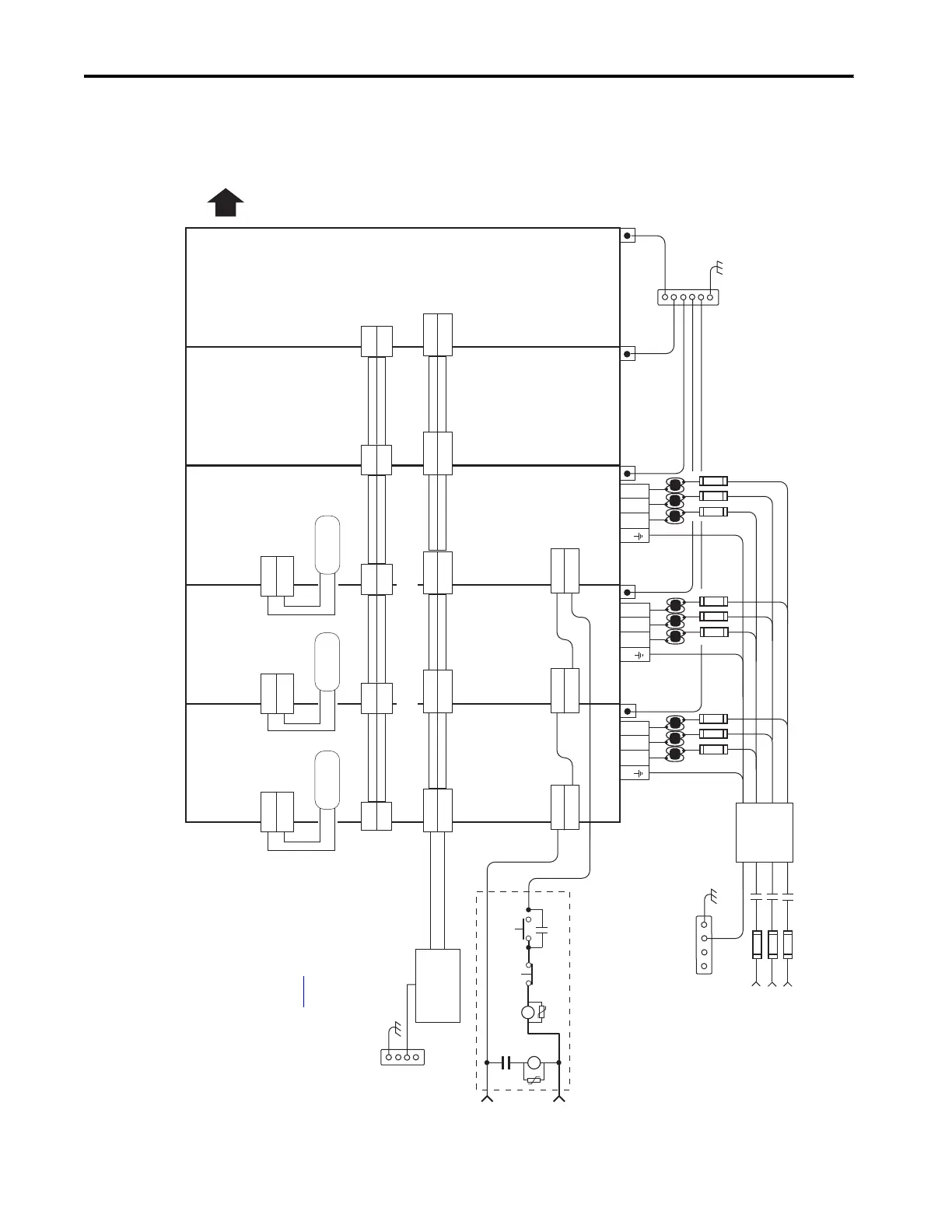
In this example, the inverter drives and optional capacitor modules are downstream of three DC-bus (converter) power
supplies. When two or three DC-bus power supplies are used, they must be catalog number 2198-P208. This
configuration provides more power (kW) to the drive system.
Figure 167 - DC-bus Power Supply (multiple converters) Configuration
L3 L2 L1
24V_COM
+24V
2
1
24V_COM
+24V
24V_COM
+24V
DC+
DC-
DC+
DC-
DC+
DC-
EN+
EN–
CONT EN+
CONT EN–
24V_COM
+24V
DC+
DC-
24V_COM
+24V
DC+
DC-
DC+
SH
L3 L2 L1
L3 L2 L1
DC+
SH
DC+
SH
CONT EN+
CONT EN–
CONT EN+
CONT EN–
324…528V AC rms
Three-phase Input
Notes 1, 2
Bonded Cabinet Ground Bus *
Control Power
(CP) Connectors
Three-phase Input
(IPD) Connectors
* Indicates User Supplied Component
Chassis
Customer Supplied
+24V DC
Power Supply *
Refer to table on page 341
for note information.
DC Bus
(DC) Connectors
2198-P208
DC-bus Power Supply
Circuit Protection *
Note 2
2198-P208
DC-bus Power Supply
2198-P208
DC-bus Power Supply
2198-Sxxx -ERSx or
2198-Dxxx -ERSx
Inverter
2198-Sxxx -ERSx or
2198-Dxxx -ERSx
Inverter
Bonded Cabinet Ground Bus *
PE Ground
Note 11
PE Ground
Note 11
PE Ground
Note 11
PE Ground
Note 11
PE Ground
Note 11
1321-3R80-B
Line Reactors
(required components)
2198-TCON-24VDCIN36
24V Input Power
Wiring Connector
2198-H070-P-T
T-connector and Bus Bar
2198-H070-P-T
T-connector and Bus Bar
2198-xxxx-P-T
T-connector and Bus Bar
2198-xxxx-P-T
T-connector and Bus Bar
Shunt Power
(RC) Connector
Internal Shunt
Note 14
Shunt Power
(RC) Connector
Internal Shunt
Note 14
Shunt Power
(RC) Connector
Internal Shunt
Note 14
STOP *
START *
CR1 *
CR1 *
CR1 *
M1 *
Notes 13,18
24V AC/DC
50/60 Hz
Refer to Attention statement (Note 17).
Bonded Cabinet
Ground Bus *
Additional Inverters,
Capacitor Modules, or
DC-bus Conditioner
Modules
Grounding Screws/Jumpers
Note 15
Contactor Enable
(CED) Connectors
Note 18
M1 Contactor
Note 13
Note 8
Note 8
2198-DBR200-F
Three-phase
AC Line Filter
Note 5
When three 2198-P208 DC-bus power supplies are connected in parallel, two
additional 2198-BARCON-85DC200 bus-links must be ordered separately.
Circuit
Protection*
Note 2
 Loading...


