Rockwell Automation Publication 2198-UM002G-EN-P - February 2019 345
Interconnect Diagrams Appendix A
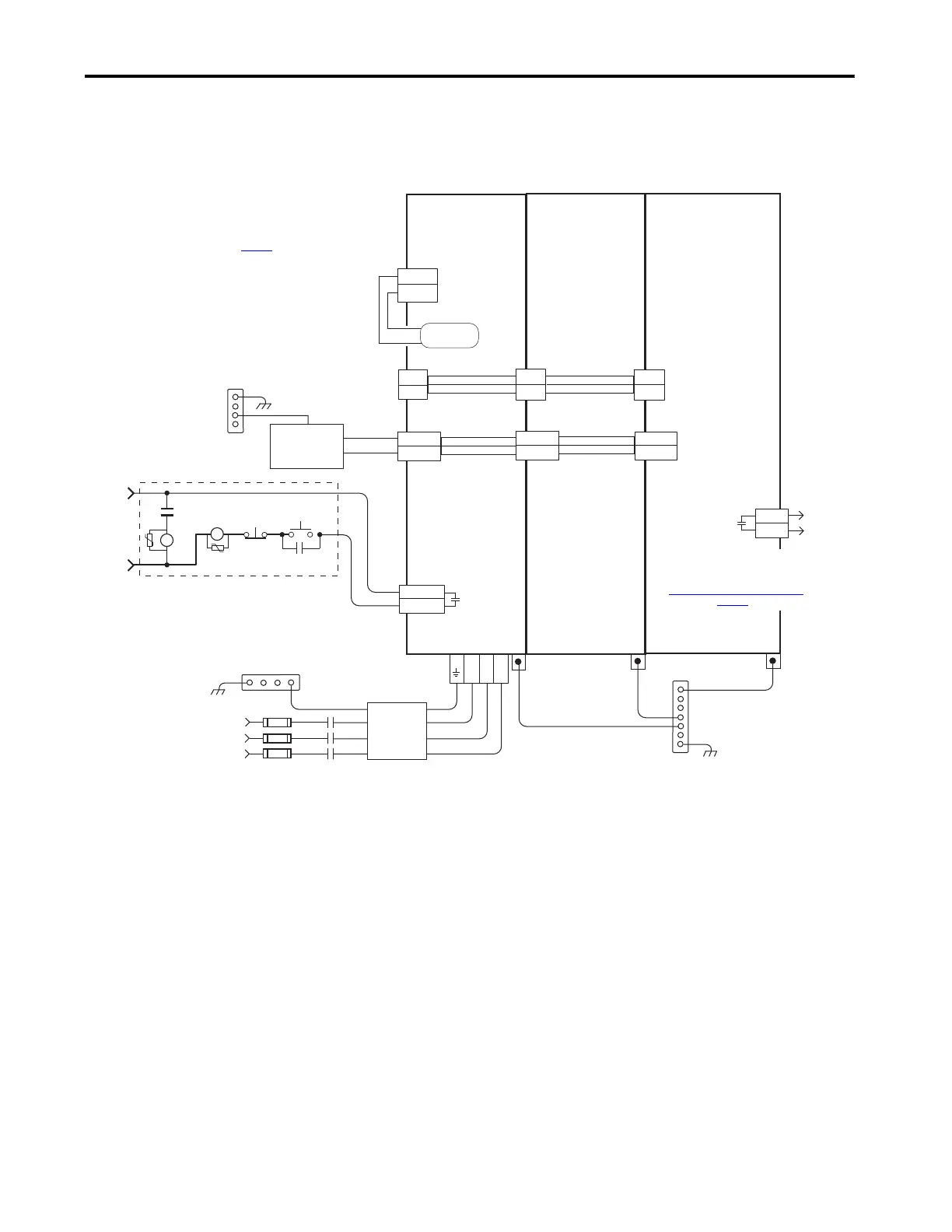
In this example, the 2198-CAPMOD-2240 capacitor module is included for
energy storage and to improve dynamic performance.
Figure 168 - DC-bus Power Supply with Capacitor Module
MS
MS
L3 L2 L1
24V_COM
+24V
2
1
DC+
DC-
EN+
EN–
CONT EN+
CONT EN–
DC+
SH
24V_COM
+24V
DC+
DC-
24V_COM
+24V
DC+
DC-
2
1
2198-CAPMOD-2240
Capacitor Module
Refer to table on page 341 for note information.
2198-Pxxx
DC-bus Power Supply
2198-Sxxx -ERSx or
2198-Dxxx -ERSx
Inverter
Bonded Cabinet Ground Bus *
Chassis
Customer Supplied
+24V DC
Power Supply *
STOP *
START *
CR1 *
CR1 *
CR1 *
M1 *
Notes 13,18
24V AC/DC
50/60 Hz
Refer to Attention statement (Note 17).
324…528V AC rms
Three-phase Input
Notes 1, 2
Three-phase Input
(IPD) Connectors
PE Ground
Note 11
PE Ground
Note 11
PE Ground
Note 11
Bonded Cabinet
Ground Bus *
2198-TCON-24VDCIN36
24V Input Power
Wiring Connector
2198-xxxx-P-T
T-connector and Bus Bar
2198-H040-P-T
T-connector and Bus Bar
Shunt Power
(RC) Connector
Internal Shunt
Note 14
Bonded Cabinet
Ground Bus *
* Indicates User Supplied Component
Circuit
Protection*
Note 2
Control Power
(CP) Connectors
DC Bus
(DC) Connectors
M1
Contactor
Note 13
Contactor Enable
(CED) Connectors
Note 18
Grounding Screws/Jumpers
Note 15
Note 8
Monitor capacitor module status by
wiring to digital input Bus Capacitor OK
or Logix 5000™ controller. Refer to
Capacitor Module Status Wiring Example
on page 357, for an example.
Module
Status (MS)
Connector
2198-DBRxx-F
Three-phase
AC Line Filter
Note 5
 Loading...


