346 Rockwell Automation Publication 2198-UM002G-EN-P - February 2019
Appendix A Interconnect Diagrams
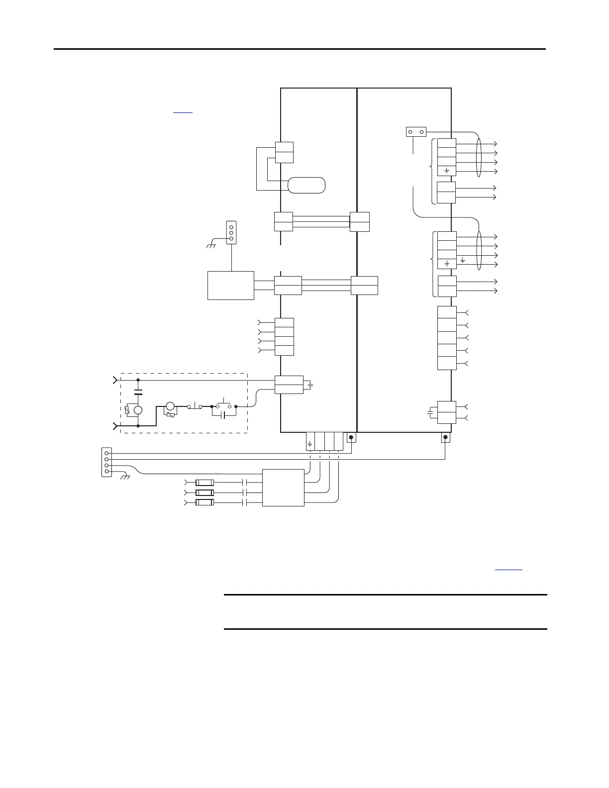
Figure 169 - DC-bus Power Supply (single iTRAK power supply) Configuration
(26) AC (EMC) line filter can be required for CE compliance. Place line filter as close to the drive as possible and do not route very dirty
wires in wireway. If routing in wireway is unavoidable, use shielded cable with shields grounded to the drive chassis and filter
case. For AC line filter specifications, refer to Kinetix Servo Drives Specifications Technical Data, publication KNX-TD003
.
2198-DBRxx-F line filters are preferred.
EN+
EN–
+24V
24V_COM
+24V
24V_COM
1
2
DC+
DC-
DC+
DC-
DC+
SH
1
2
3
4
5
24V COM
24V COM
SHIELD
DC–
L
H
1
2
3
4
CONT EN+
CONT EN–
IN1
COM
IN2
SHLD
1
2
3
4
ENABLE
COM
COM
SHLD
1
2
1
2
DC-
L
H
A
B
24V +
24V -
24V+
24V–
–
+
CLEAR
FAULT
RDY–
RDY+
L3 L2 L1
1
2
3
Bonded Cabinet
Ground Bus *
Control Power
(CP) Connectors
Three-phase Input
(IPD) Connector
Chassis
Customer Supplied
+24V DC
Power Supply *
DC Bus
(DC) Connectors
2198-P070
Kinetix 5700
DC-bus Power Supply
2198T-W25K-ER
Kinetix 5700
iTRAK Power Supply
Contactor Enable
(CED) Connector
2198T-W25K-P-T
T-connectors and Bus Bars
Shunt Power
(RC) Connector
DC Power Bus A
to iTRAK
Motor Modules
Cable Shield
Clamp
Note 7
Digital Input
(IOD) Connector
Digital Input
(IOD) Connector
Note 9
2198-TCON-24VDCIN36
24V Input Power
Wiring Connector
DC Power Bus B
to iTRAK
Motor Modules
Control Power A
to iTRAK
Motor Modules
Control Power B
to iTRAK
Motor Modules
iTRAK Power Supply
Ready (IR) Connector
PE Ground
Note 11
PE Ground
Note 11
* Indicates User Supplied Component
324…528V AC rms
Three-phase Input
Notes 1, 2, 4
2198-DBRxx-F
(26)
Three-phase
AC Line Filter
Refer to Attention statement (Note 17).
Bonded Cabinet
Ground Bus *
Notes 13,18
Circuit
Protection*
Note 2
M1
Contactor
Note 13
STOP *
START *
CR1 *
CR1 *
CR1 *
M1 *
24V AC/DC
50/60 Hz
Refer to table on page 341
for note information.
Grounding Screws/Jumpers
Note 15
Internal Shunt
Note 14
DC-bus Power Output A
(IDC) Connector
and Control Power Output A
(ICP) Connector
DC-bus Power Output B
(IDC) Connector
and Control Power Output B
(ICP) Connector
IMPORTANT The 2198-RPxxx regenerative bus supply can replace the 2198-Pxxx DC-bus
power supply in systems with the iTRAK power supply.
 Loading...


