2198-Sxxx -ERSx or
2198-Dxxx -ERSx
Inverter
PE Ground
Note 11
PE Ground
Note 11
PE Ground
Note 11
Bonded Cabinet Ground Bus *
* Indicates User Supplied Component
2198-DCBUSCOND-RP312
DC-bus Conditioner Modules
PE Ground
Note 11
PE Ground
Note 11
PE Ground
Note 11
2198-Sxxx -ERSx or
2198-Dxxx -ERSx
Inverter
2198-Sxxx -ERSx or
2198-Dxxx -ERSx
Inverter
2198-Sxxx -ERSx or
2198-Dxxx -ERSx
Inverter
Refer to table on page 341 for note information.
Control Power
(CP) Connectors
DC Bus
(DC) Connectors
Control Power
(CP) Connectors
DC Bus
(DC) Connectors
Bonded Cabinet Ground Bus *
PE Ground
Note 11
PE Ground
Note 11
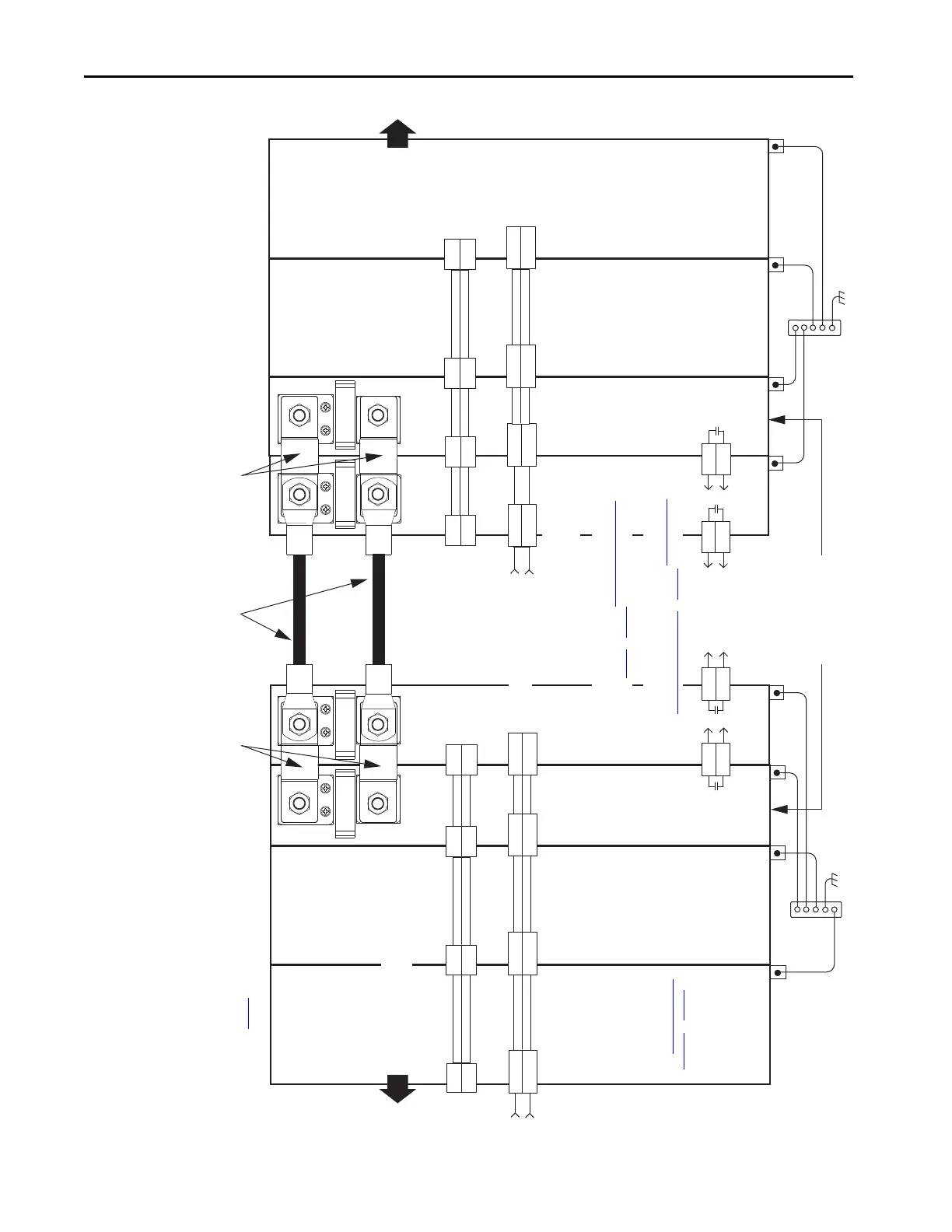
Flexible Bus-bars
Flexible Bus-bars
Customer-supplied External DC-bus
Wire Lug Connections
2198-xxxx-P-T
T-connectors
and Bus Bars
Additional Inverters and/or
Kinetix 5700 System Power Supply
Additional Inverters
2198-TCON-24VDCIN36
24V Input Power
Wiring Connector
Note 8
Note 8
Note 8
Note 8
Module
Status (MS)
Connector
Module
Status (MS)
Connector
2198-CAPMOD-2240
Capacitor Modules
Monitor capacitor module status by wiring to digital input Bus Capacitor
OK or Logix 5000 controller. Refer to Capacitor Module Status Wiring
Example on page 357, for an example.
Monitor DC-bus conditioner module status by wiring to digital input Bus
Conditioner OK or Logix 5000 controller. Refer to DC-bus Conditioner
Module Status Wiring Example on page 357, for an example.
AT TE NT IO N: Circuit protection can
be added after the power supply
cluster to help protect converters
and inverters from damage due to
a DC-bus cable short-circuit.
2198-H040-P-T
T-connector
and Bus Bar
2198-xxxx-P-T
T-connectors
and Bus Bars
2198-xxxx-P-T
T-connectors
and Bus Bars
2198-H040-P-T
T-connector
and Bus Bar
2198-H040-P-T
T-connector
and Bus Bar
2198-TCON-24VDCIN36
or 2198T-W25K-P-IN
24V Input Power
Wiring Connector
Use 2198T-W25K-P-IN input
wiring connector with 2198-
S263-ERSx and 2198-S312-ERSx
drives. Use 2198-TCON-
24VDCIN36 input wiring
connector with all other drives.
See CP Connector Wiring -
Shared Bus on page 146 for
wiring specifications.
 Loading...


