352 Rockwell Automation Publication 2198-UM002G-EN-P - February 2019
Appendix A Interconnect Diagrams
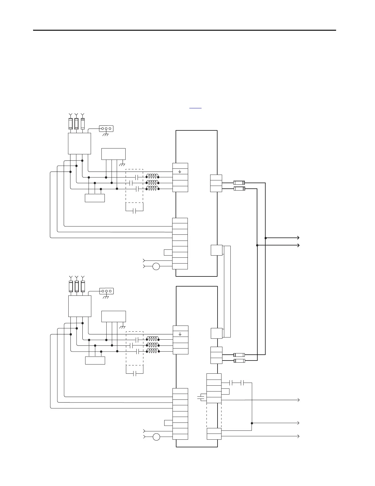
In this example, three-phase AC input power is fed to two 8720MC-RPS065
units in a leader/follower configuration. The DC-bus (TB1) terminals
connect to the Kinetix 5700 DC-bus via the DC-bus conditioner module
because the system current exceeds 104 A.
Figure 175 - 8720MC-RPS065 Leader/Follower Units with Kinetix 5700 Drive System
E/N
L1
L2
L3
G
R
S
T
TB1
L1 AUX
L2 AUX
L3 AUX
PR1
PR2
PR3
MC1
MC2
TB2
R1
S1
T1
MC
TB1
DC+
DC-
P
N
R S T
E/N
L1
L2
L3
G
R
S
T
TB1
L1 AUX
L2 AUX
L3 AUX
PR1
PR2
PR3
MC1
MC2
TB2
R1
S1
T1
MC
TB1
DC+
DC-
P
N
TB3
MC
0V
COM
RDY
+24V DC
PWR
R S T
CN3
CN2
MC *
Note 12
Note 16
8720MC-RPS065
Regenerative
Power Supply
(Follower)
324…506V AC rms
Three-phase Input
Note 3
Bonded Cabinet
Ground Bus *
Three-phase
AC Line Filter
Note 5
* Indicates User Supplied Component
Harmonic
Filter
Varistor
Line
Reactors
Circuit
Protection *
Customer
Supplied
120V AC
Refer to table on page 341
for note information.
Circuit
Protection *
Note 23
MC *
Note 12
Note 16
8720MC-RPS065
Regenerative
Power Supply
(Leader)
324…506V AC rms
Three-phase Input
Note 3
Bonded Cabinet
Ground Bus *
Three-phase
AC Line Filter
Note 5
Harmonic
Filter
Varistor
Line
Reactors
Circuit
Protection *
Customer
Supplied
120V AC
Circuit
Protection *
Contactor *
Note 12
Note 23
Aux Contact
MC1
MC1
Power
Interface
Board
Power
Interface
Board
DC Bus to
Kinetix 5700 Drive System
Regeneration OK
to Digital Inputs
Aux Contact to
Control String
Note 6
Note 6
Aux Contact
MC2
MC2
 Loading...


