192 Rockwell Automation Publication 2094-UM002G-EN-P - August 2016
Chapter 7 Configure and Start the Kinetix 6500 Drive System
4. Type 2.0 as the number of revolutions for the test or another number
more appropriate for your application.
5. Determine your need for a hardware enable input at IOD-41 on the I/O
connector.
Digital input 1 (IOD-41) is configured as Enable in the Logix Designer
application by default. You may have changed that on page 181
.
6. Apply Hardware Enable Input signal for the axis you are testing.
7. Click the desired tab (Marker/Motor Feedback/Motor and Feedback).
In this example, the Motor and Feedback test is chosen.
8. Click Start.
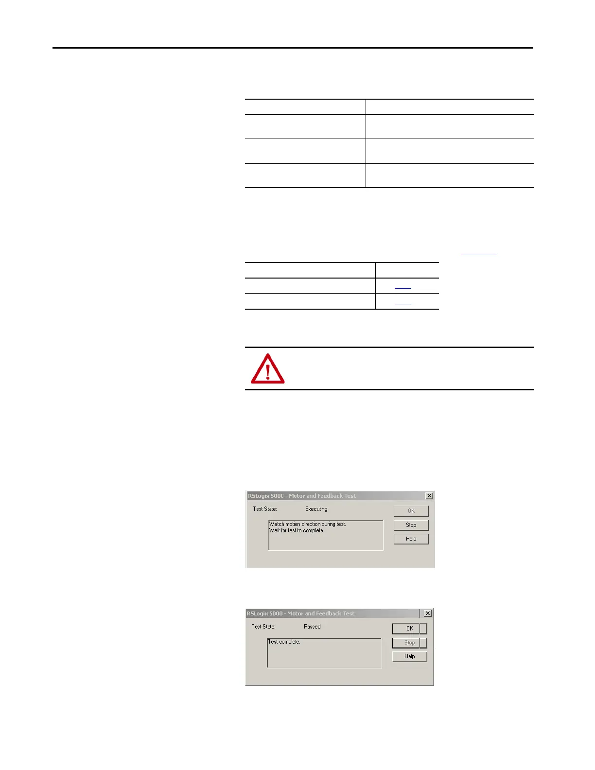
The RSLogix 5000 - Motor and Feedback Test dialog box opens. The
Test State is Executing.
When the test completes successfully, the Test State changes from
Executing to Passed.
This Test Performs this Test
Marker
Verifies marker detection capability as you rotate the motor
shaft.
Motor Feedback
Verifies feedback connections are wired correctly as you
rotate the motor shaft.
Motor and Feedback
Verifies motor power and feedback connections are wired
correctly as you command the motor to rotate.
If Digital Input 1 is configured as Then
Enable Go to step 6
.
Unassigned Go to step 7.
ATTENTION: To avoid personal injury or damage to equipment,
apply 24V ENABLE signal only to the axis you are testing.

 Loading...


