56 Rockwell Automation Publication 2094-UM002G-EN-P - August 2016
Chapter 3 Mount the Kinetix 6200 and Kinetix 6500 Drive System
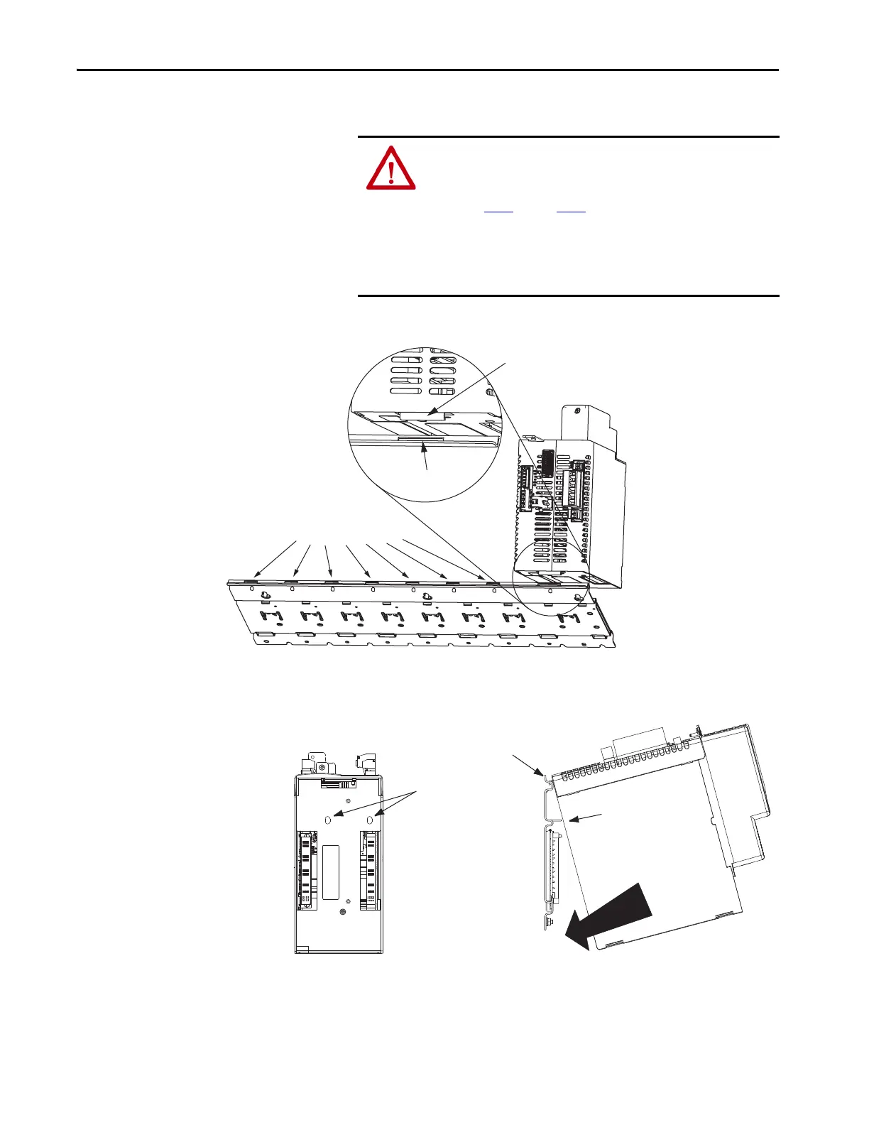
2. Determine the next available slot and module for mounting.
3. Hang the mounting bracket from the slot on the power rail.
4. Pivot module downward and align the guide pins on the power rail with
the guide pin holes in the back of the module.
ATTENTION: To avoid damage to the pins on the back of each IAM,
AM, IPIM, shunt, and slot-filler module and to make sure that
module pins mate properly with the power rail, hang modules as
shown in step 3
through step 6.
The power rail must be mounted vertically on the panel before
hanging modules on the power rail. Do not mount modules if the
power rail is horizontal.
Power Rail
IAM or AM Power Module, IPIM,
Shunt, or Slot-filler Module
(IAM power module is shown)
Slots for additional axis modules,
shunt module, or slot-filler modules.
Power Rail Slot
Mounting Bracket
Guide Pin
Holes
Power rail (side view)
in upright vertical position.
Guide Pins
Pivot module downward
and align with guide pins.
IAM or AM Power Module, IPIM,
Shunt, or Slot-filler Module, Side View
(IAM power module is shown)
IAM or AM Power Module, IPIM,
Shunt, or Slot-filler Module, Rear View
(AM power module is shown)

 Loading...


