Rockwell Automation Publication 2094-UM002G-EN-P - August 2016 57
Mount the Kinetix 6200 and Kinetix 6500 Drive System Chapter 3
5. Gently push the module against the power rail connectors and into the
final mounting position.
6. Use 2.26 N•m (20 lb•in) torque to tighten the mounting screws.
Repeat step 1
through step 6 for each AM, IPIM, shunt, or slot-filler module in
your Bulletin 2094 drive system
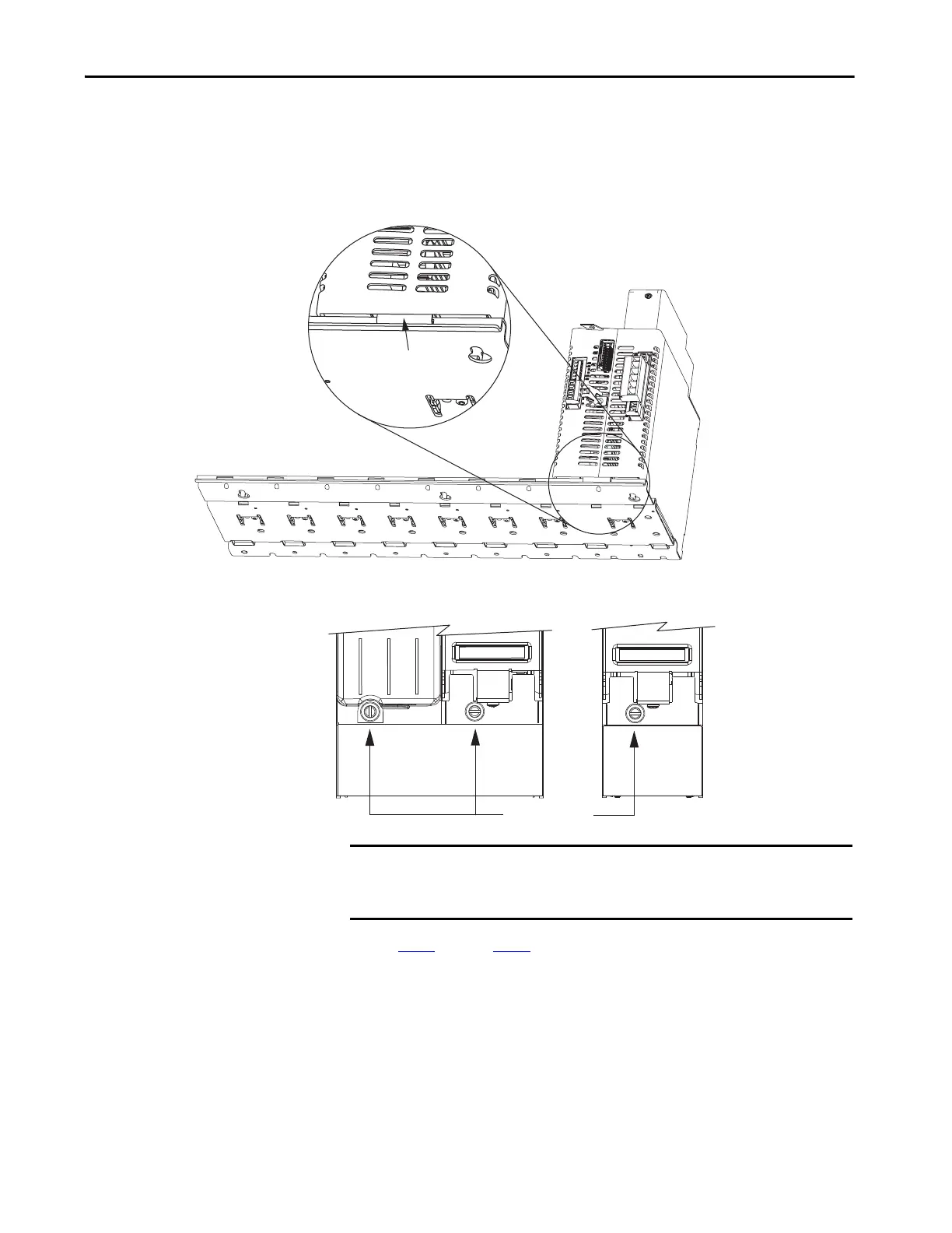
TIP The IAM module can have two or three power rail connectors and guide
pins, the AM module can have one or two, all other modules have one.
Power Rail
Bracket secured in slot.
IAM or AM Power Module, IPIM,
Shunt, or Slot-filler Module
(IAM power module is shown)
Bottom front view of the
double-wide IAM or AM power module.
(AM power module is shown).
Mounting Screws
Bottom front view of the
single-wide AM, IPIM, shunt,
or slot-filler module
(AM power module is shown).
IMPORTANT There are two mounting screws when mounting 2094-BC04-M03-M, and
2094-BC07-M05-M (double-wide) IAM modules, and 2094-BM03-M and
2094-BM05-M (double-wide) AM modules.

 Loading...


