64 Rockwell Automation Publication 2094-UM002G-EN-P - August 2016
Chapter 4 Connector Data and Feature Descriptions
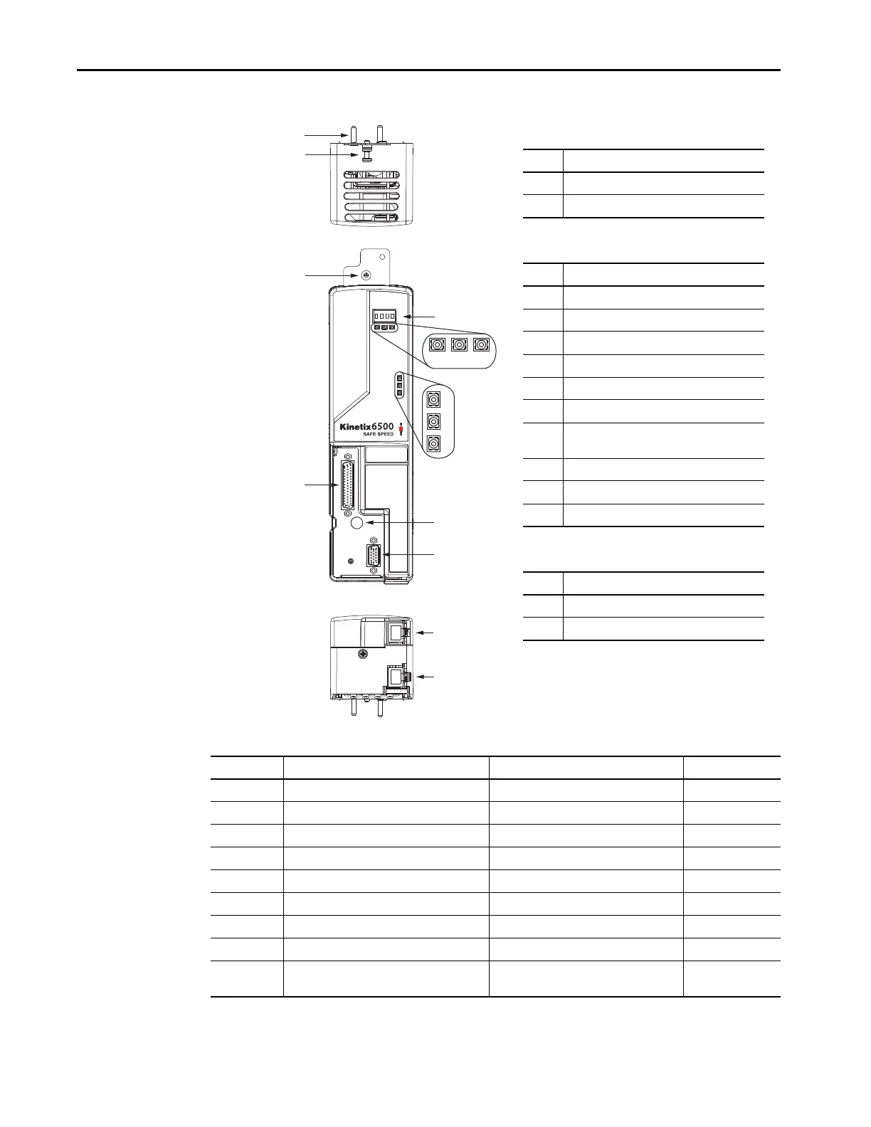
Figure 29 - Control Module Features and Indicators (Ethernet)
Table 22 - Kinetix 6200 and Kinetix 6500 Power Module and Control Module Connectors
2
3
2
7
4
5
6
1
10
12
11
13
9
8
14
Item Description
1 Guide pins (2x)
2Captive screw
Item Description
3 Four-character status display
4PORT 1 status indicator
5PORT 2 status indicator
6 Module status indicator
7Network status indicator
8 DC bus status indicator
9
Safety lock status indicator
(2094-EN02D-M01-S1 modules only)
10 I/O, safety, and aux feedback (IOD) connector
11 Power module mounting screw access hole
12 Motor feedback (MF) connector
Item Description
13 Ethernet (PORT1) connector
14 Ethernet (PORT2) connector
Kinetix 6500
Control Module, Top View
(2094-EN02D-M01-S1 is shown)
Kinetix 6500
Control Module, Front View
(2094-EN02D-M01-S1 is shown)
Kinetix 6500
Control Module, Bottom View
(2094-EN02D-M01-S1 is shown)
Designator Description Connector Module
IOD User I/O (drive), safety, and auxiliary feedback 44-pin high-density D-shell (female) Control
MF Motor feedback 15-pin high-density D-shell (female) Control
CPD Control input power (drive) 2-position plug/header IAM
IPD VAC input power (drive) and DC bus 6-position plug/header IAM
CED Contactor enable 2-position plug/header IAM
MP Motor power 4-position plug/header IAM/AM
BC Motor/Resistive brake 6-position plug/header IAM/AM
Tx and Rx Sercos transmit and receive Sercos fiber-optic (2) Control
PORT1 and
PORT2
EtherNet/IP network RJ-45 Ethernet (2) Control

 Loading...


