Publication 2711P-UM001B-EN-P
5-12 Installing and Replacing Components
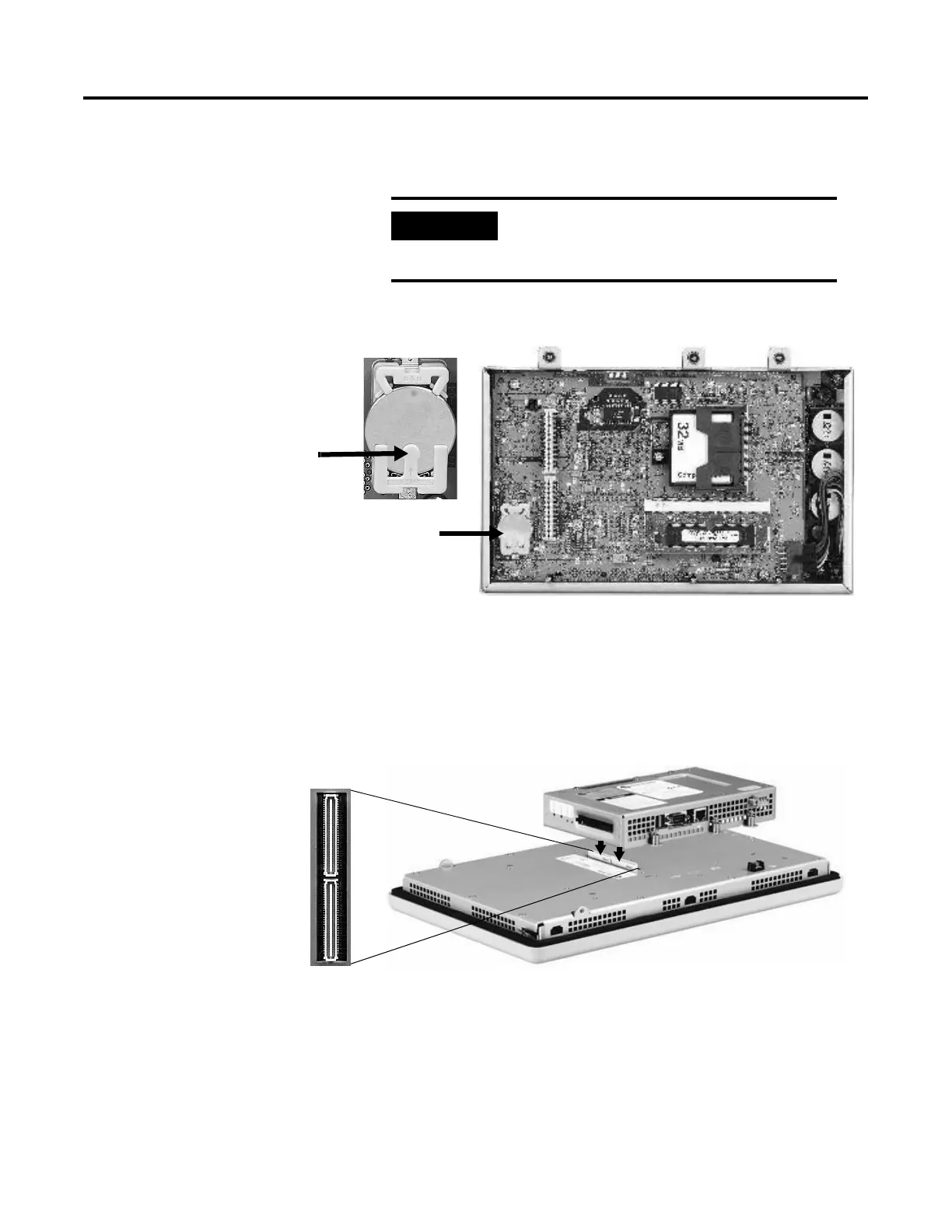
5. Carefully lift the Logic Module away from the terminal and flip
over to expose the circuit board.
6. Locate the battery on the circuit board.
7. Press down firmly on the middle part of battery retainer clip.
The battery will pop out.
8. Slide the new battery under the 3-prong holder and push down.
9. Attach the Logic Module by aligning the 2 connectors on the
bottom of the module align with the connectors on the terminal.
10. Push down on the Logic Module until firmly seated.
11. Tighten the 6 captive screws that secure the Logic Module to a
torque of .68 N•m (6-8 in-lb).
12. Attach the Communication Module (if necessary) and tighten the
4 screws to a torque of .68 N•m (6-8 in-lb).
IMPORTANT
Wear a properly ground ESD wristband
before touching any of the electronic
components in the Logic Module.
Battery
Press down
here to pop
battery out.

 Loading...


