Rockwell Automation Publication 2711P-UM006E-EN-P - January 2017 141
Terminal Connections Chapter 6
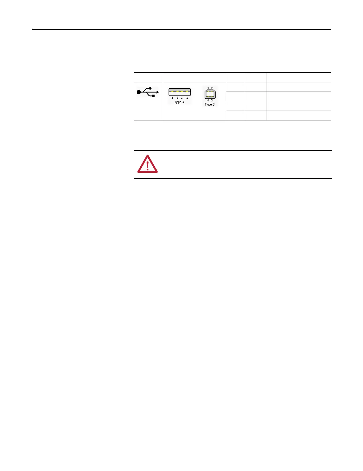
The USB ports are identified by a USB icon. Each USB host port supports 0.5 A
at 5V DC. Connected USB devices must not exceed this power load.
Hi-speed USB 2.0 certified cables are recommended for error-free transmissions.
Connect only externally-powered USB hubs to the terminal. Before attaching
devices to a USB hub, make sure the power adapter is connected and powered on.
Table 62 - USB Connector Pinouts
USB Icon USB Ports Pin Signal Description
1VCC+5V
2D- Data -
3D+Data +
4 GND Ground
WARNING: USB devices not powered by the USB port must be within same
enclosure as the terminal. USB devices must be connected to a ground system
common with the terminal or used with a USB hub providing galvanic isolation.
 Loading...