142 Rockwell Automation Publication 2711P-UM006E-EN-P - January 2017
Chapter 6 Terminal Connections
Ethernet Connections
The Ethernet port connects to a controller on an EtherNet/IP network by using
standard Ethernet and network connections. The port also supports application
transfers, and printing.
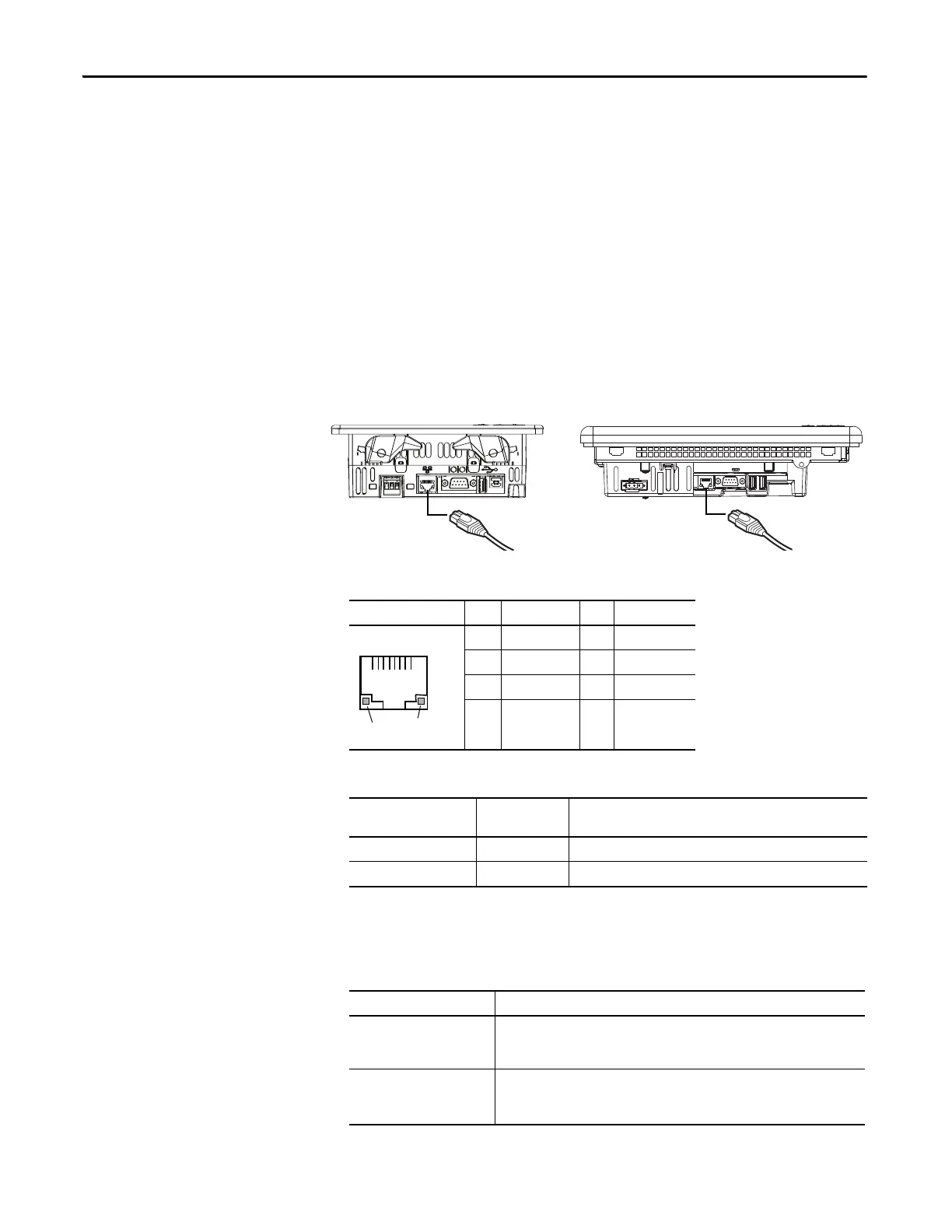
Ethernet Connector
The Ethernet port has an RJ45, 10/100Base-T connector for network
communication and supports MDI/MDI-X connections.
Figure 15 - Ethernet Connector
Ethernet Cable
The 2711P-RN20 Ethernet communication module is available for the
700 to 1500 terminals if another Ethernet port is required. The module has its
own unique IP address.
Table 63 - Ethernet Connector Pinout
Connector Pin Pin Name Pin Pin Name
RJ45 Connector 1 Transmit + 5 Unused
2 Transmit – 6 Receive –
3 Receive + 7 Unused
4Unused 8Unused
Table 64 - Ethernet Status Indicators
Indicator Status Indicator
Color
Description
Link Integrity Yellow Asserted when a link is present.
Activity Status Indicator Green Pulsed active when receive or transmit activity is present.
Table 65 - Ethernet Cable Requirements
For These Terminal Models Use this Ethernet Cable
700 to 1500 terminals Belden 7921A shielded CAT5E cable according to TIA 568-B.1 and RJ45 connector
according to IEC 60603-7 for compliance with Marine emission limits and the
European Union 89/336/EEC EMC Directive.
400 to 600 terminals Use category five, twisted-pair cables.
You can use a standard Ethernet cable or a crossover cable, such as catalog number
2711P-CBL-EX04, when connecting directly to a logic controller or switch.
1
8
Yel low
indicator
Green
indicator
 Loading...