132 Rockwell Automation Publication 2711P-UM006E-EN-P - January 2017
Chapter 5 Install and Replace Components
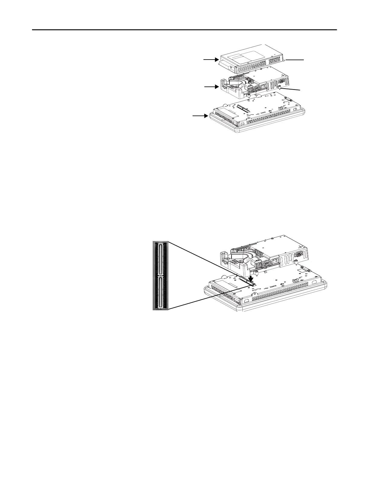
5. Carefully lift the logic module away from the terminal and turn over to
expose the circuit board.
6. Locate the battery on the circuit board.
7. Remove the battery by lifting up the side of the battery.
The battery can be removed up to 15 seconds without losing clock and
calendar data.
8. Insert the new battery.
9. Reattach the logic module by aligning the two connectors on the bottom
of the logic module with the connectors on the back of the display module.
10. Push down on the logic module until it is firmly seated.
11. Tighten the four captive screws that secure the logic module to a torque of
0.58 N•m (5…7 lb•in).
12. Reattach the communication module, if necessary, and tighten the four
screws to a torque of 0.58 N•m (5…7 lb•in).
Install the AC Power Supply
Module
The AC power supply module for the 400 and 600 terminals, catalog number
2711P-6RSA, attaches to the back of a DC-powered terminal to convert the
terminal from DC to AC power. You can install the AC module with the
terminal mounted in the panel. No special tools are needed.
Communication Module
Display Module
Captive Screw
Screw
Logic Module
 Loading...