Rockwell Automation Publication 2711P-UM006E-EN-P - January 2017 33
Install Terminal Chapter 2
Mount the 400/600 Terminal
in a Panel
The terminals were designed for single-person installation. No tools are required
except for those needed to make the panel cutout
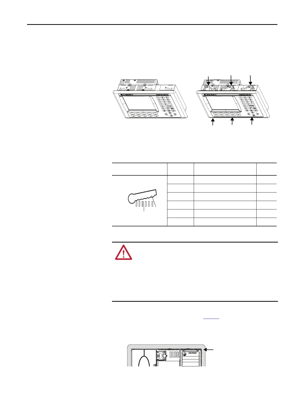
Mounting levers secure the terminal to the panel. Four or six levers are required
depending on the terminal model. The levers insert into the mounting slots on
the top and bottom of the terminal.
Each mounting slot has six notches with alignment marks that are locking
positions for a lever. The thickness of the panel in which you mount the terminal
determines the locking position required to maintain the NEMA/UL Type seal.
Follows these steps to mount the terminal in a panel.
1. Cut an opening in the panel by using the cutout template shipped with the
terminal or the cutout dimensions on page 30
.
2. Verify the sealing gasket is present on the terminal.
This gasket forms a compression type seal. Do not use sealing compounds.
Table 35 - Lever Locking Positions
Mounting Slot
Lever Lock
Position
Panel Thickness Range
Typical
Gauge
1
1.50…2.01 mm (0.060…0.079 in.) 16
2
2.03…2.64 mm (0.080…0.104 in.) 14
3
2.67…3.15 mm (0.105…0.124 in.) 12
4
3.17…3.66 mm (0.125…0.144 in.) 10
5
3.68…4.16 mm (0.145…0.164 in.) 8/9
6
4.19…4.80 mm (0.165…0.188 in.) 7
ATTENTION:
Disconnect all electrical power from the panel before making the panel cutout.
Make sure the area around the panel cutout is clear and that the panel is clean of
any debris, oil, or other chemicals.
Make sure metal cuttings do not enter any components already installed in the
panel and that the edges of the cutout have no burrs or sharp edges.
Failure to follow these warnings can result in personal injury or damage to panel
components.
1
2
3
4
5
6
Notch
Alignment Marks
Orientation of Slot Varies
 Loading...