42 Rockwell Automation Publication 2711P-UM006E-EN-P - January 2017
Chapter 2 Install Terminal
Connect AC Power
Follow these steps to connect the terminal to AC power.
1. Verify that the terminal is not connected to a power source.
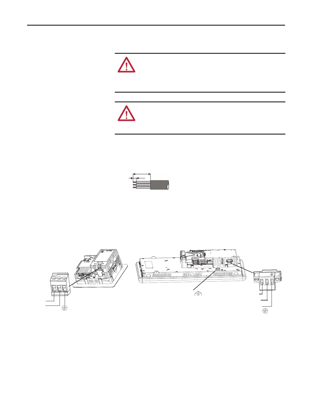
2. Strip 7 mm (0.28 in.) of insulation from the ends of the wires.
3. Secure the AC power wires to the marked terminals (L1 and L2N) on the
power terminal block.
4. Secure the protective earth/ground wire to the marked position on the
power terminal block.
5. On 700 to 1500 terminals, also secure the functional earth/ground wire to
the functional earth screw on the back of display to ground bus.
6. Apply power to the terminal.
WARNING: Explosion Hazard
Do not disconnect equipment unless power has been switched off and area is
known to be nonhazardous.
Disconnect all power before installing or replacing components. Failure to
disconnect power can result in electrical shock or damage to the terminal.
ATTENTION: Improper wiring of the power terminals can result in voltage at
the communication connector shells.
Do not apply power to the terminal until all wiring is connected. Failure to do so
can result in electrical shock.
L1
L2N/Neutral
Protective Earth
to Ground Bus
Functional Earth/Ground
L1 L2N
to Ground Bus
L1
L2N/Neutral
Protective Earth to Ground Bus
400 or 600 Terminal 700 to 1500 Terminal
 Loading...