Rockwell Automation Publication 6000-TG100A-EN-P - September 2020 31
Chapter 3 Component Inspection and Test Procedures
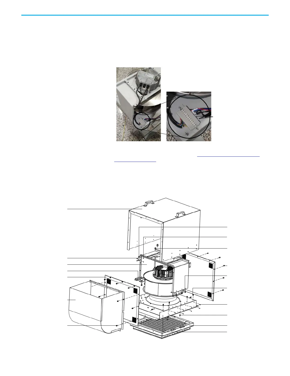
Replace Fan for A-Frame Fan Housing
To replace an EC400 fan, you need to change the wiring so that the fan runs at
a different speed than what it does for the B-Frame drive.
1. Remove the three terminals in the front that are secured on the terminal
block in the fan housing, as shown.
2. Install the new wires of the resistor in reverse order of removal.
3. After you have changed the wiring, see Replace Fan for B-Frame Fan
Housing on page 32 for instructions on how to replace the fan.
To replace an EC500 fan, follow these instructions:
1. Remove the four M6 x 16 hexagon combination screws that secure the
noise reduction barrier, and remove the barrier.
Wires of resistor to
change fan speed
M6 x 16 hexagon
combination screw (4)
Noise reduction barrier
Fan housing lid
M10 x 25 socket screw (6)
M4 nut, washer, and lock
washer (8)
M4 x 12 hexagon
combination screw (8)
Fan support bracket
Wire screen frame
Fan housing bracket
M6 x 16 hexagon
combination screw (14)
M8 x 20 hexagon
combination screw (8)
M6 x 16 hexagon combination
screw (12)
M4 x 10 countersunk head
screw (18)
M6 x 16 hexagon
combination screw (6)
Horizontal louver
Fan housing assembly
Terminal block
 Loading...


