EasyManuals Logo
Home>Allen-Bradley>DC Drives>PowerFlex 6000T

Allen-Bradley PowerFlex 6000T Hardware Service Manual

Allen-Bradley PowerFlex 6000T
70 pages
To Next Page IconTo Next Page
To Previous Page IconTo Previous Page
Page #34 background imageLoading...
Page #34 background image
34 Rockwell Automation Publication 6000-TG100A-EN-P - September 2020
Chapter 3 Component Inspection and Test Procedures
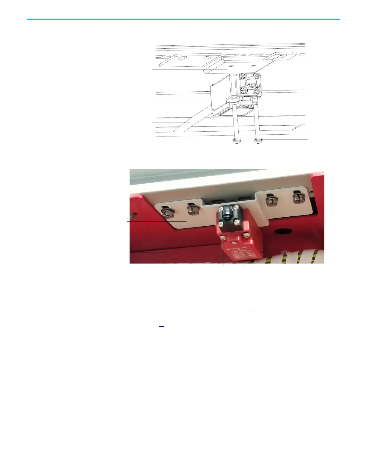
Figure 6 - Replace Door Position Limit Switch, A-Frame
Figure 7 - Replace Door Position Limit Switch, B-Frame
Component Fuse Tests Follow these steps to check the fuses for other components/modules.
1. Review the Product Advisories on page 11
.
2. Remove power from the system. See Remove Power from the System on
page 13
.
3. Continuity test the fuse or fuses.
4. Replace a fuse as necessary.
M4 x 30 bolt
Limit Switch
Aviation plug
Mounting bracket
M4 x 35 bolt Aviation plug
Mounting bracket
Limit Switch

Table of Contents

Other manuals for Allen-Bradley PowerFlex 6000T

Questions and Answers:

Question and Answer IconNeed help?

Do you have a question about the Allen-Bradley PowerFlex 6000T and is the answer not in the manual?

Allen-Bradley PowerFlex 6000T Specifications

General IconGeneral
BrandAllen-Bradley
ModelPowerFlex 6000T
CategoryDC Drives
LanguageEnglish

Related product manuals