46 Rockwell Automation Publication 6000-TG100A-EN-P - September 2020
Chapter 4 LV Control Cabinet
Control Pod Fan Assembly
Replacement
Replace the control pod fan assembly with kit catalog number
SK-RM-PODFAN1-F8.
Follow these steps to replace the control pod fan assembly.
1. Review the Product Advisories on page 11
.
2. Remove power from the system. See Remove Power from the System on
page 13
.
3. Open the control bay enclosure door.
4. Remove the control pod cover. See Control Pod Cover Removal on
page 35
.
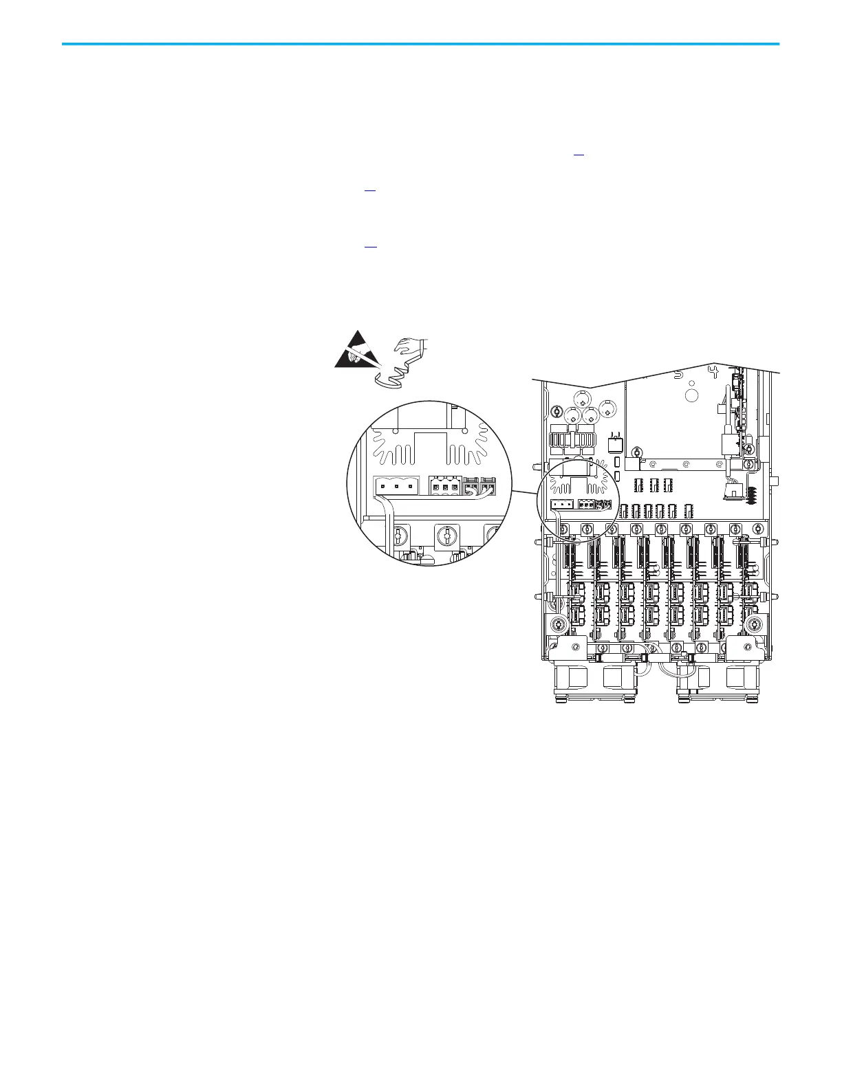
5. Disconnect the two fan power supply connectors from connectors J18
and J25 on the fiber-optic interface board.
6. Remove the harness from the cable supports on the side of the pod
chassis.
7. Loosen the two captive thumbscrews on the fan assembly and pull the
assembly out and off the pod chassis.
 Loading...


