Rockwell Automation Publication 6000-TG100A-EN-P - September 2020 45
Chapter 4 LV Control Cabinet
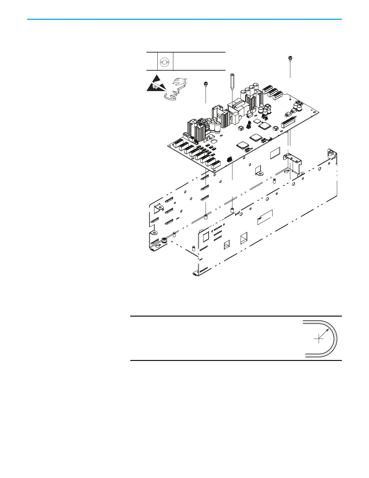
14. Rotate the left side of Smart Fiber interface circuit board away from the
control pod so that the board clears the mounting tab on right sidewall of
the control pod. Remove the board from the control pod.
15. To install the Smart Fiber interface circuit board, perform the operation
in the reverse order of removal.
When installing the fiber-optic cables:
1. Without bending the cable to a radius less than 50 mm (2 in.), fully insert
the fiber-optic cable into the transceiver.
2. Insert the transceiver and fiber-optic cable into the connector on the
board, until you hear an audible ‘click.’
IMPORTANT
Minimum inside bend radius for fiber-optic cable is 50
mm (2 in.). Any bends with a shorter inside radius can
permanently damage the fiber-optic cable. Signal
attenuation increases as inside bend radius is
decreased.
12
M4 x 8 mm
T20 or F - 6.4 mm (0.25 in.)
2.6 N•m (23 lb•in)
 Loading...


