38 Rockwell Automation Publication 6000-TG100A-EN-P - September 2020
Chapter 4 LV Control Cabinet
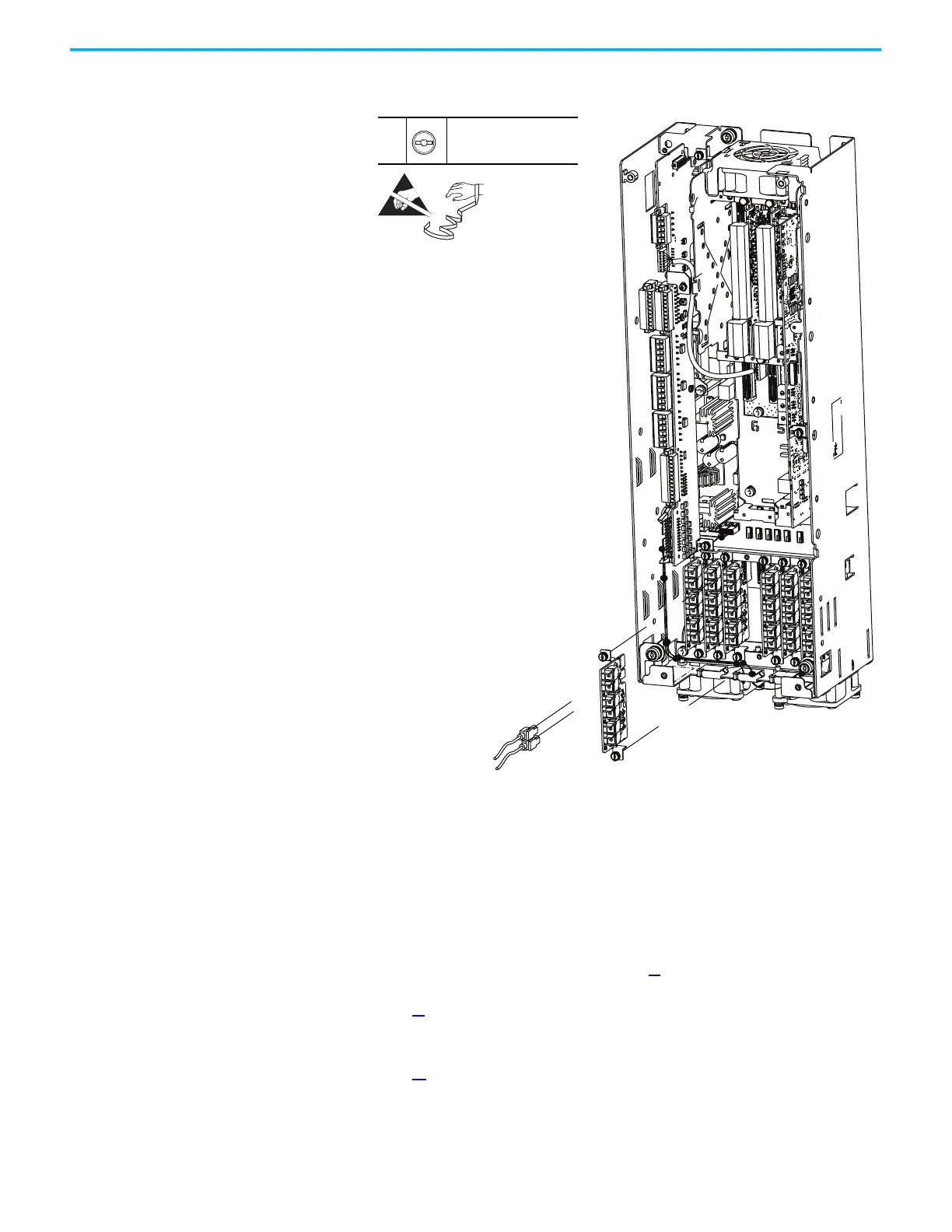
6. Loosen the two captive thumbscrews that secure the board and fiber-
optic cables to the chassis and remove the board and cables.
7. For each fiber-optic cable, remove the cable from the transceiver.
8. To install the fiber transceiver circuit board, perform the operation in the
reverse order of removal.
Main Control Circuit Board
Replacement
Replace a main control circuit board with kit part number PN-579785.
Follow these steps to replace the main control circuit board.
1. Review the Product Advisories on page 11
.
2. Remove power from the system. See Remove Power from the System on
page 13
.
3. Open the control bay enclosure door.
4. Remove the control pod cover. See Control Pod Cover Removal on
page 35
.
6
–
T15 or F - 5 mm (0.19 in.)
0.45 N•m (4 lb•in)
 Loading...


