Rockwell Automation Publication 6000-TG100A-EN-P - September 2020 43
Chapter 4 LV Control Cabinet
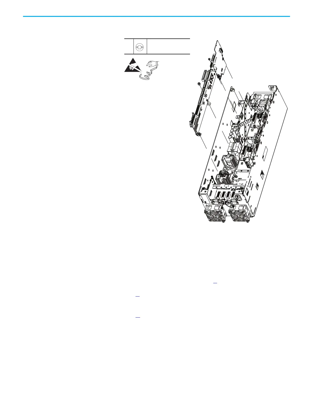
6. Loosen the three captive thumbscrews and remove the two loose screws
that secure the power I/O board to the smart fiber interface circuit board.
7. To install the power I/O board, perform the operation in the reverse
order of removal.
Smart Fiber Interface
Circuit Board Replacement
Replace a Smart Fiber interface circuit board with kit part number PN-579787.
Follow these steps to replace the Smart Fiber interface circuit board.
1. Review the Product Advisories on page 11
.
2. Remove power from the system. See Remove Power from the System on
page 13
.
3. Open the control bay enclosure door.
4. Remove the control pod cover. See Control Pod Cover Removal on
page 35
.
5. Disconnect connector P14 from connector J14 on the Smart Fiber
interface circuit board.
7
M4 x 8 mm
T20 or F - 5 mm (0.19 in.)
2.6 N•m (23 lb•in)
 Loading...


