44 Rockwell Automation Publication 6000-TG100A-EN-P - September 2020
Chapter 4 LV Control Cabinet
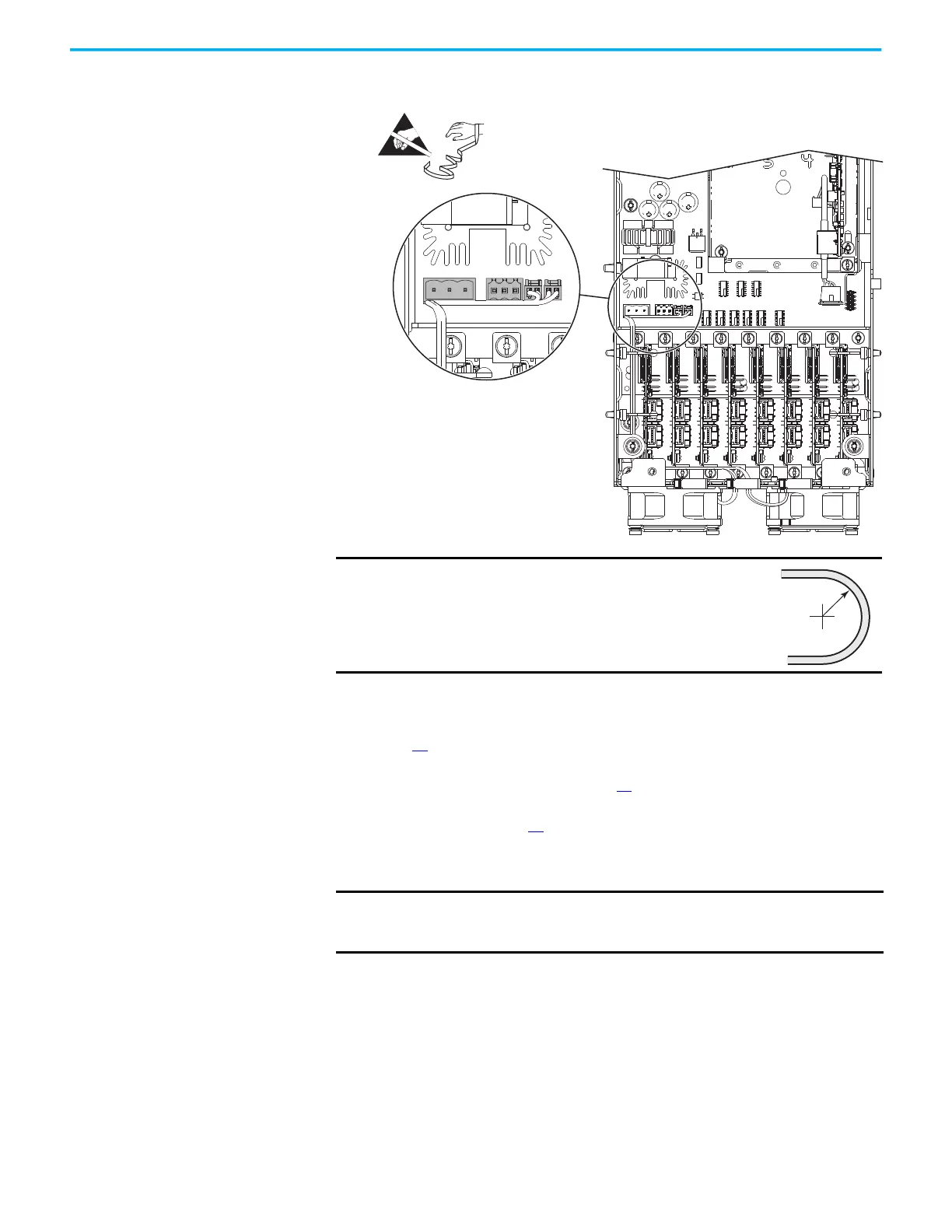
6. Disconnect the two fan power supply connectors from connectors J18
and J25 on the Smart Fiber interface circuit board.
7. Remove the fiber-optic cables from the cable management devices in the
control pod.
8. Remove the power I/O board. See Remove the Power I/O Board on
page 42
.
9. Remove the fiber transceiver circuit board. See Remove the Fiber
Transceiver Circuit Board on page 37
.
10. Remove the main control circuit board. See Main Control Circuit Board
Replacement on page 38
.
11. Remove the four M4 x 8 mm screws that secure the control pod chassis to
the standoffs on the control panel, then remove control pod chassis.
12. Remove the three M4 x 8 mm long screws that secure the Smart Fiber
interface circuit board to the control pod.
13. Move the Smart Fiber interface circuit board slightly upward toward top
of the control pod, so that keyholes on board clear the mounting posts
and lift off the board.
IMPORTANT
Minimum inside bend radius for fiber-optic cable is 50
mm (2 in.). Any bends with a shorter inside radius can
permanently damage the fiber-optic cable. Signal
attenuation increases as inside bend radius is
decreased.
IMPORTANT The four M4 x 8 mm screws that secure the control pod chassis to the
control panel are not retentive. Take steps to be sure that the screws do
not fall into the drive below.
 Loading...


