Rockwell Automation Publication 6000-TG100A-EN-P - September 2020 35
Chapter 4
LV Control Cabinet
Control Pod Cover Removal You must remove the control pod cover to access other components inside
the pod.
Follow these steps to remove the control pod cover.
1. Review the Product Advisories on page 11
.
2. Remove power from the system. See Remove Power from the System on
page 13
.
3. Open the control bay enclosure door.
4. Loosen, but do not remove, the bottom two M4 x 8 mm slotted-torx
screws that secure the cover to the assembly.
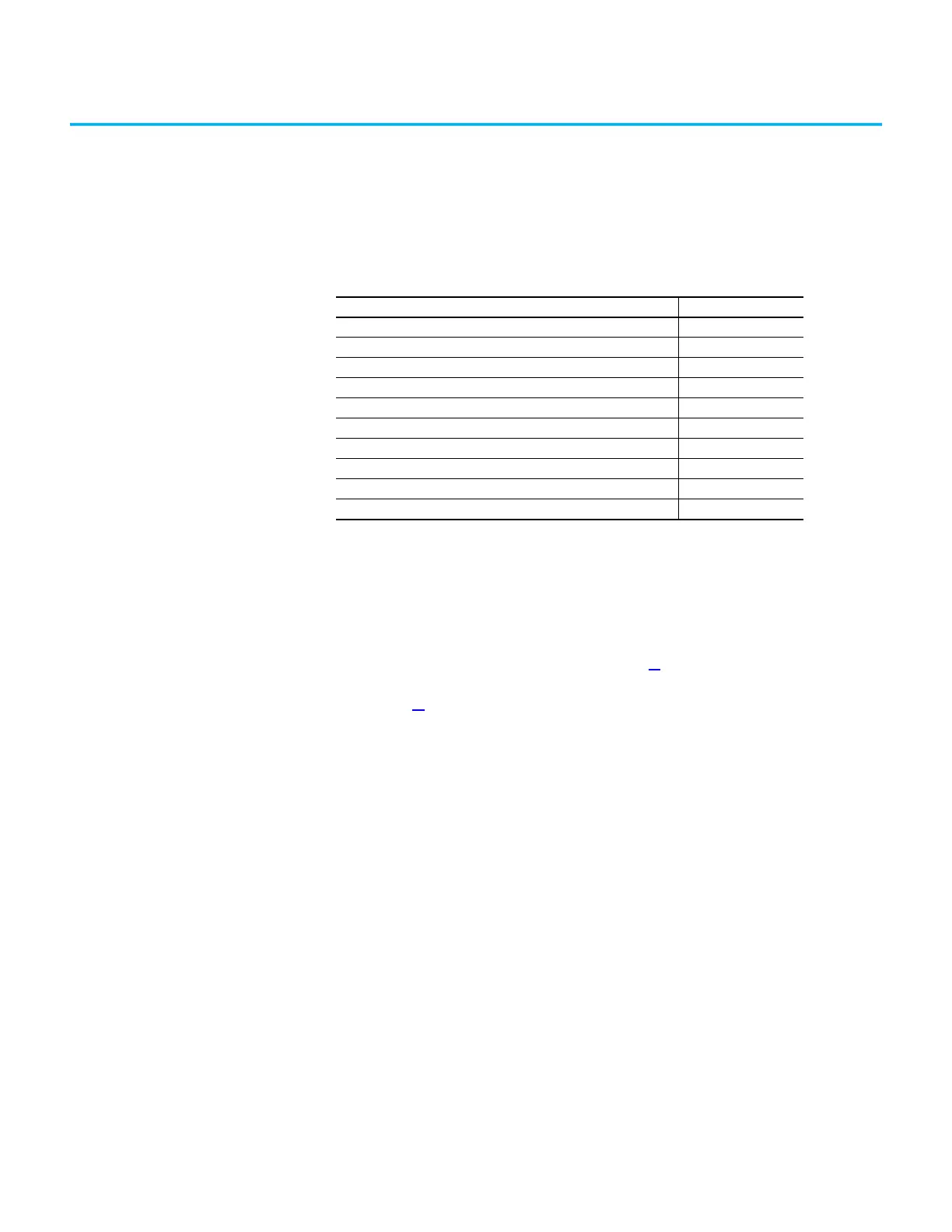
Topic Page
Control Pod Cover Removal 35
Fiber Transceiver Circuit Board Replacement 37
Main Control Circuit Board Replacement 38
Backplane Circuit Board Replacement 41
Power I/O Board Replacement 42
Smart Fiber Interface Circuit Board Replacement 43
Control Pod Fan Assembly Replacement 46
Control Pod Replacement 47
Inspect the Integrated Touch Screen Display 50
Replace the Integrated Touch Screen Display 50
 Loading...


