36 Rockwell Automation Publication 6000-TG100A-EN-P - September 2020
Chapter 4 LV Control Cabinet
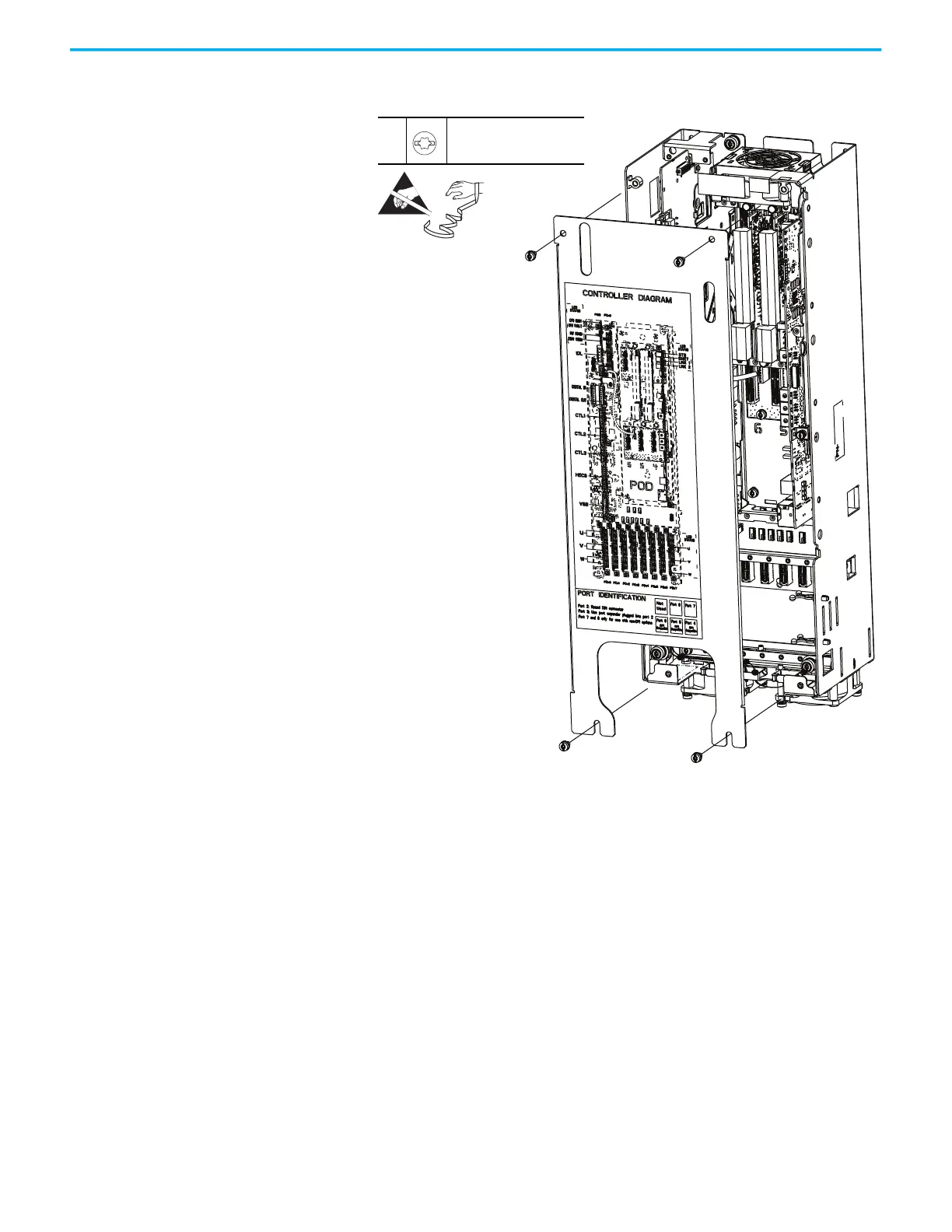
5. Remove the top two M4 x 8 mm slotted-torx screws that secure the cover
to the assembly and remove the cover.
6. To install the control pod cover, perform the operation in the reverse
order of removal.
The Control Pod is shown separated
from the Control/Input Bay to clarify
the instructions only.
4, 5
M4 x 8 mm
T20 or F - 6.4 mm (0.25 in.)
2.6 N•m (23 lb•in)
 Loading...


