Rockwell Automation Publication 6000-TG100A-EN-P - September 2020 55
Chapter 5 Isolation Transformer Cabinet
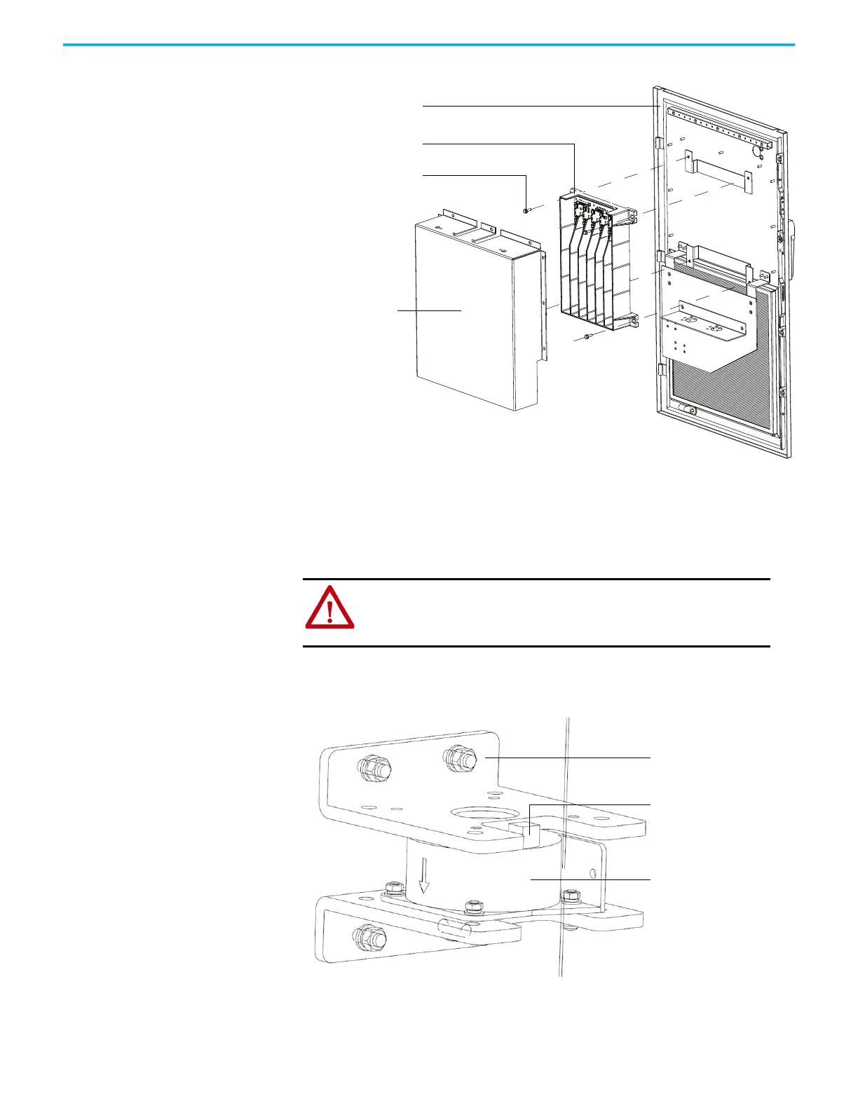
5. Install the new VSB in the reverse order of removal.
Inspect/Replace HECS There are three current sensors that are located inside the Isolation Transformer
cabinet. Verify that the current sensor wire connector is properly seated. Check for
obvious signs of damage.
1. Unplug the Current Sensor Connector from the HECS.
Figure 8 - HECS for A-Frame
M8 x 30 bolts and
washers (4)
VSB
Junction cabinet front door
VSB PC cover
ATTENTION: To prevent electrical shock, disconnect the main power
before working on the drive. Verify that all circuits are voltage-free,
using a hot stick or appropriate high voltage-measuring device. Failure
to do so may result in injury or death.
Mounting insulation bracket
Current Sensor connection
HECS
 Loading...


