56 Rockwell Automation Publication 6000-TG100A-EN-P - September 2020
Chapter 5 Isolation Transformer Cabinet
Figure 9 - HECS for B-Frame
2. Disconnect one end of the power cable that goes through the HECS from
the Power Cell.
3. Remove the Mounting Bracket with the HECS still attached.
4. Remove and retain hardware connecting the HECS to the Mounting
Bracket.
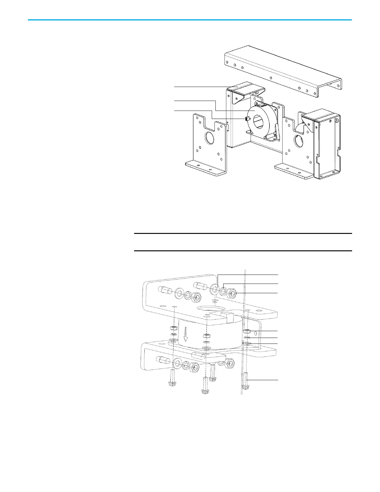
Figure 10 - Exploded view of the HECS and Mounting Bracket for A-Frame
Current Sensor connection
HECS
Mounting bracket
IMPORTANT
Note the orientation of the HECS on the bracket. The new HECS must be
installed facing the same direction.
M4 x 16 cross pan head
combination screw (4)
Ø6 lock washer (4)
M6 nut (4)
Ø6 washer (4)
M4 nut (4)
Ø4 lock washer (4)
Ø4 washer (4)
 Loading...


