Rockwell Automation Publication 6000-TG100A-EN-P - September 2020 41
Chapter 4 LV Control Cabinet
Backplane Circuit Board
Replacement
Replace a control pod backplane circuit board with kit catalog number
SK-RM-PODBP1.
Follow these steps to replace the backplane circuit board.
1. Review the Product Advisories on page 11
.
2. Remove power from the system. See Remove Power from the System on
page 13
.
3. Open the control bay enclosure door.
4. Remove the control pod cover. See Control Pod Cover Removal on
page 35
.
5. Remove the main control circuit board. See Main Control Circuit Board
Replacement on page 38
.
6. Remove the power cable from the backplane that goes to the Power I/O
Board.
7. Disconnect and remove any option modules from the backplane circuit
boards.
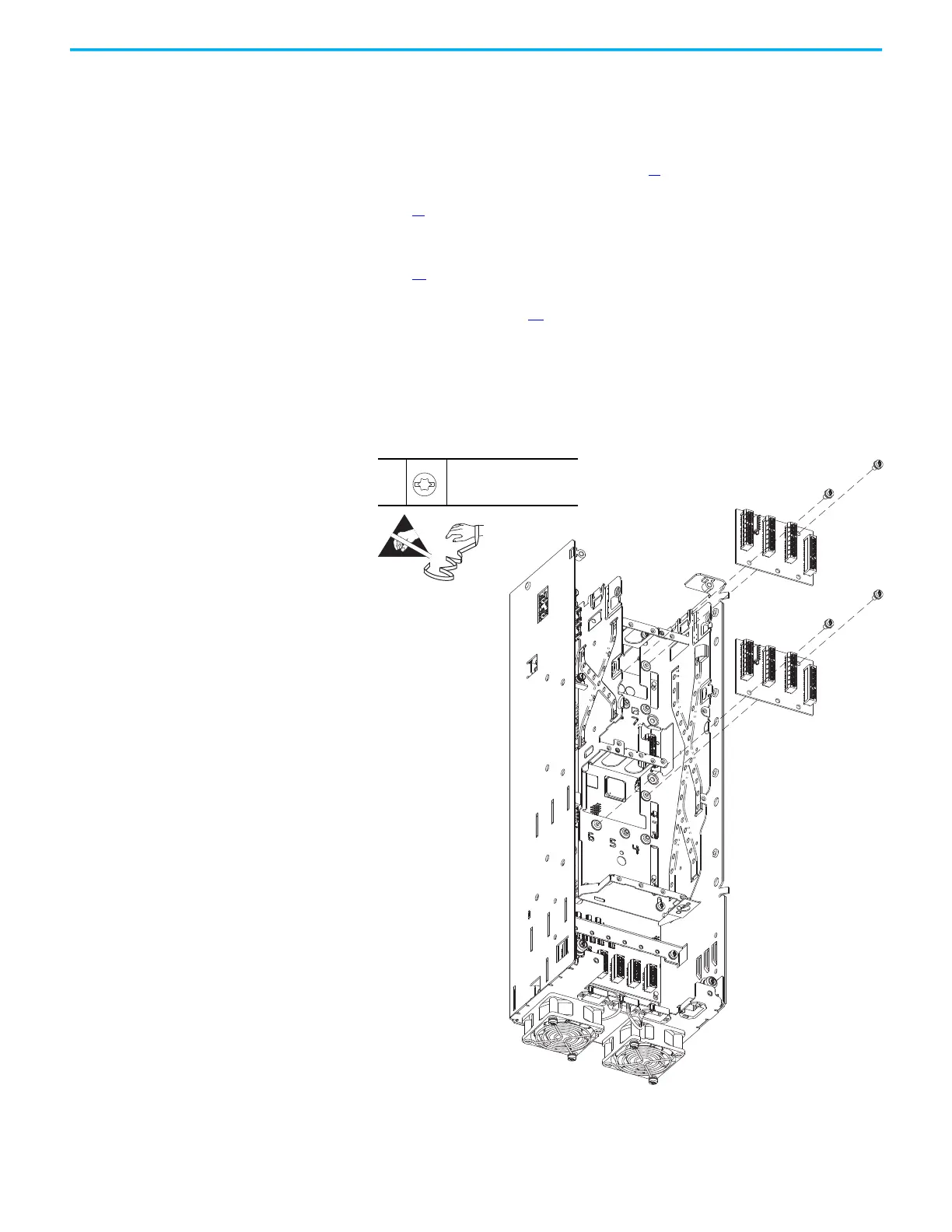
8. Remove the two M4 x 8 mm torx screws that secure the backplane circuit
board to the pod chassis and remove the board.
9. To install the backplane circuit board, perform the operation in the
reverse order of removal.
8
M4 x 8 mm
T20 or F - 5 mm (0.19 in.)
2.6 N•m (23 lb•in)
 Loading...


