40 Rockwell Automation Publication 6000-TG100A-EN-P - September 2020
Chapter 4 LV Control Cabinet
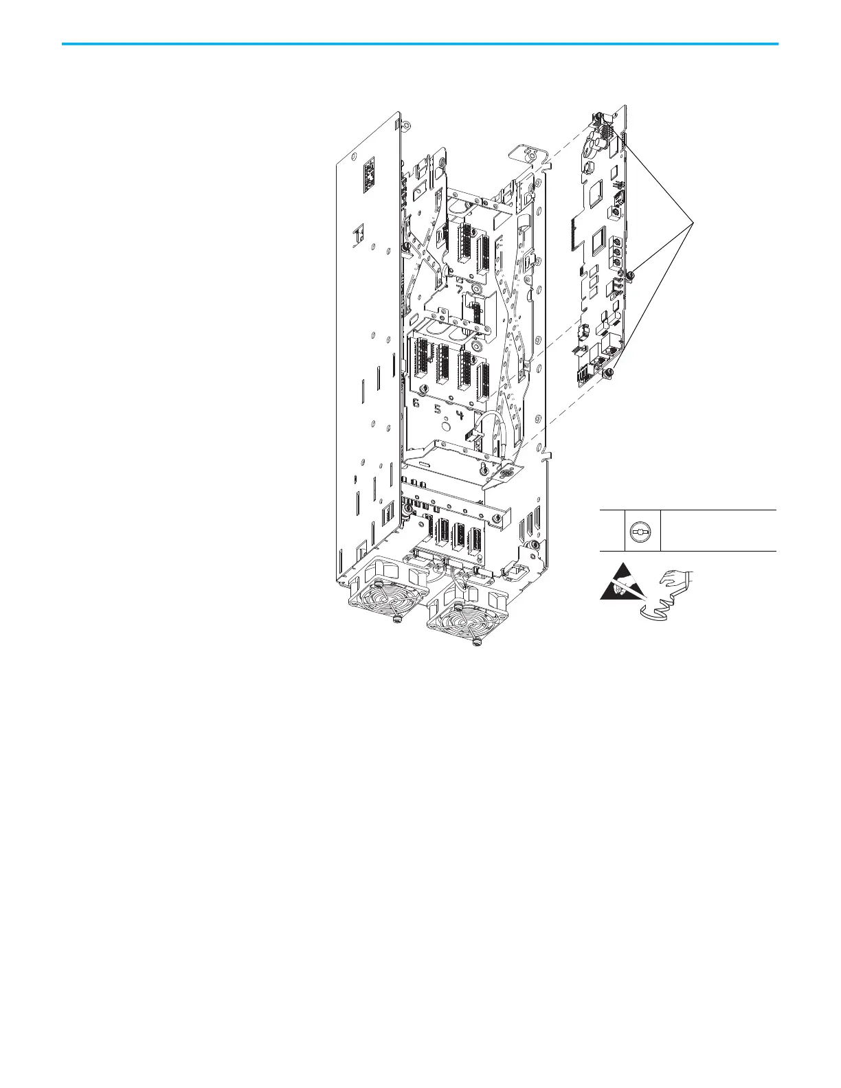
10. Loosen the three captive thumbscrews that secure the main control
board to the pod chassis and remove the board.
11. To install the main control circuit board, perform the operation in the
reverse order of removal. Check that the jumpers and switches are set the
same as the board removed.
10
–
T15 or F - 5 mm (0.19 in.)
0.45 N•m (4 lb•in)
HIM bezel not shown for clarity only.
10
 Loading...


