Rockwell Automation Publication 6000-TG100A-EN-P - September 2020 61
Chapter 6 Power Cell Cabinet
Install the Power Cell
For A-Frame Drives
For A-frame drives, install the new Power Cell in reverse order of removal.
For B-Frame Drives
For B-frame drives, follow these steps to install the Power Cell.
1. You can use the lift cart to move and position the Power Cell to the
appropriate location in the cabinet. For more information on how to use
the lift cart, see page 62
.
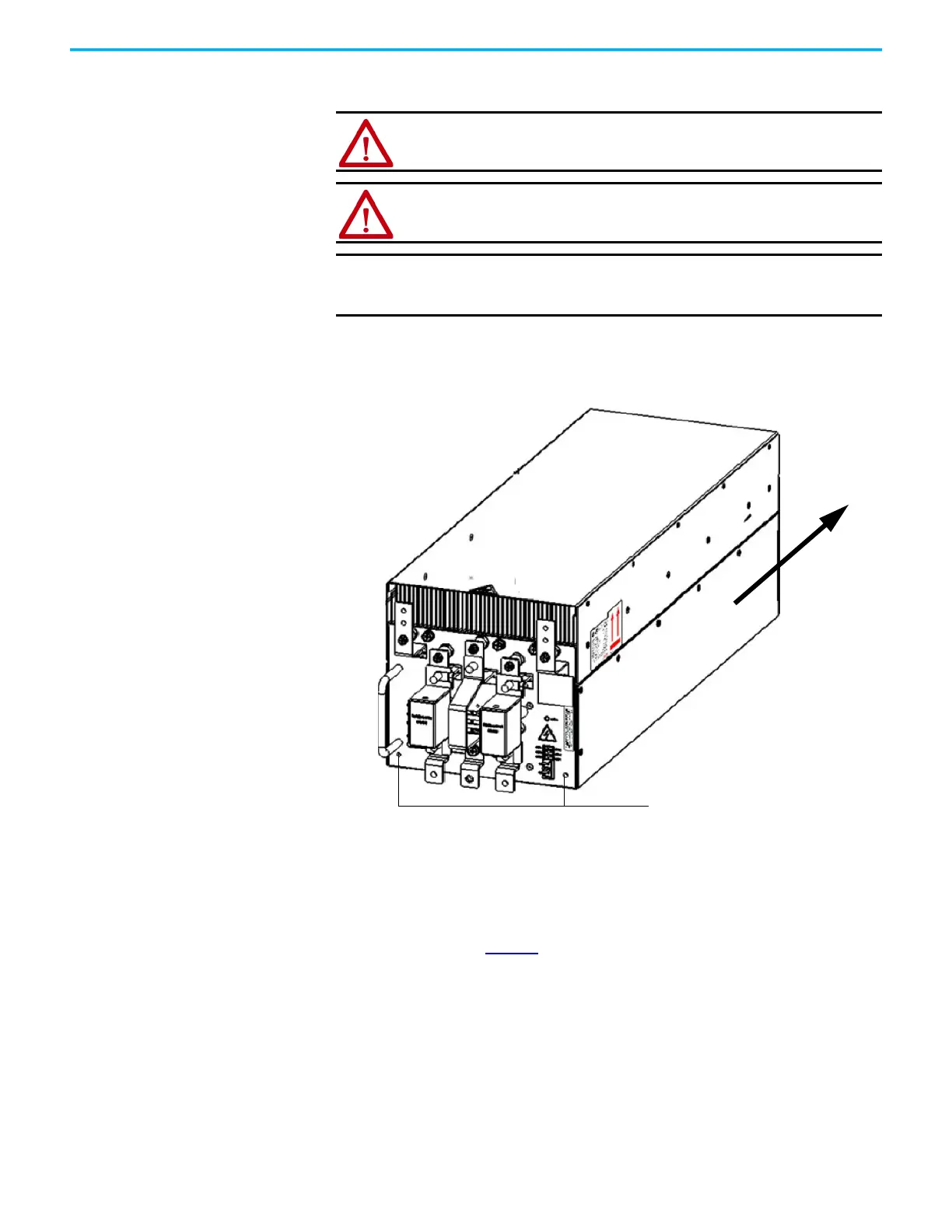
2. Push the Power Cell slowly along the guide rails until it cannot be pushed
in further.
ATTENTION: Do not use the front-mounted positioning handles for lifting
the Power Cells. They are designed to position or withdraw the Power Cell
when on the tray assembly.
ATTENTION: The Power Cell finger assemblies must be fully seated on the
cabinet stab assemblies.
IMPORTANT
The Power Cell should be handled carefully. After removing the
packaging, inspect the Power Cell to confirm that there is no damage
and moisture.
Mounting points
100/140/180/215 A rating power
cell with two fuses shown
 Loading...


