60 Rockwell Automation Publication 6000-TG100A-EN-P - September 2020
Chapter 6 Power Cell Cabinet
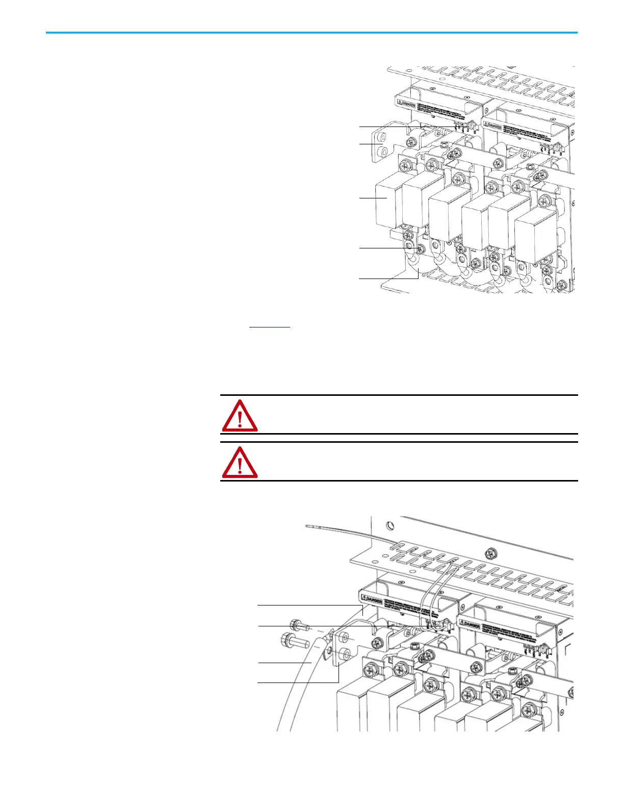
Figure 12 - Power Cell Component Location
3. Remove the output copper bars that connect adjacent Power Cells
(Figure 13
).
If the Power Cell is at the end of a row, remove the VSB and motor cable
instead of an output copper bus.
4. Disconnect the fiber-optic cables.
Figure 13 - Close up of Fiber-optic Cable Location and Power Cables
5. Carefully withdraw the Power Cell.
ATTENTION: When removing the fiber-optic cables, be careful to prevent
the cables from straining or crimping as the resulting loss in light
transmission will impact performance.
ATTENTION: Minimum bend radius that is permitted for the fiber-optic
cables is 50 mm (2.0 in.). Any bends with a shorter inside radius can
permanently damage the fiber-optic cable.
Fuse
Output copper bar
connection location
Fiber-optic cables connection point
Three-phase input cables
from isolation transformer
M6 x 16 hexagon
combination screws (2)
30/50 A rating power cells with
three fuses shown
Motor cable to
Junction cabinet
VSB cable
Output copper bar
Fiber-optic cables
30/50 A rating power cell
with three fuses shown
 Loading...


