Rockwell Automation Publication 6000-TG100A-EN-P - September 2020 49
Chapter 4 LV Control Cabinet
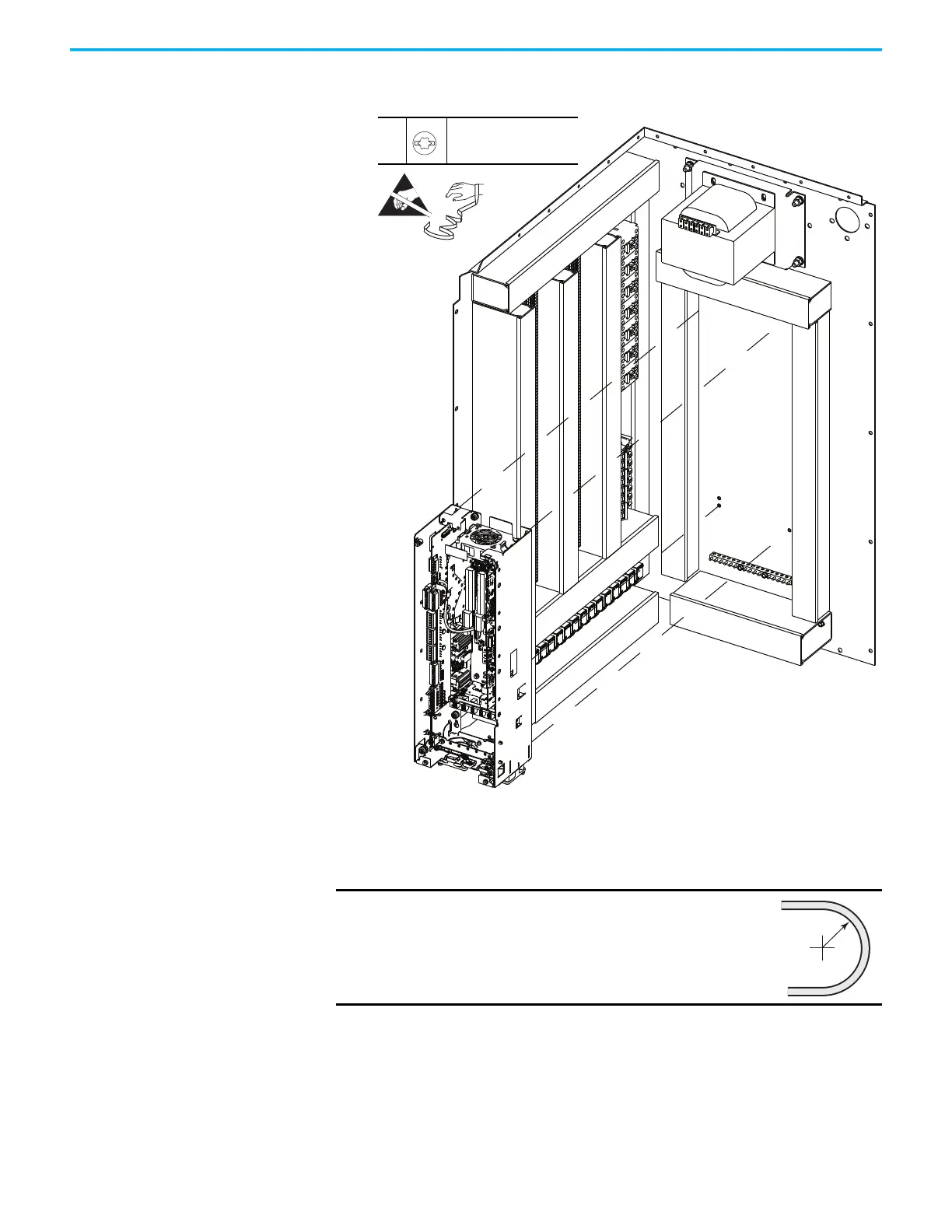
9. Slide the pod up, so that the keyholes on the pod clear the mounting
screws, and remove the control pod.
10. To install the control pod, perform the operation in the reverse order of
removal.
When installing the fiber-optic cables:
1. Without bending the cable to a radius less than 50 mm (2 in.), fully insert
the fiber-optic cable into the transceiver.
2. Insert the transceiver and fiber-optic cable into the connector on the
board, until you hear an audible ‘click.’
IMPORTANT
Minimum inside bend radius for fiber-optic cable is 50
mm (2 in.). Any bends with a shorter inside radius can
permanently damage the fiber-optic cable. Signal
attenuation increases as inside bend radius is
decreased.
7
M4 x 8 mm
T20 or F - 5 mm (0.19 in.)
2.6 N•m (23 lb•in)
 Loading...


