Rockwell Automation Publication 6000-TG100A-EN-P - September 2020 51
Chapter 4 LV Control Cabinet
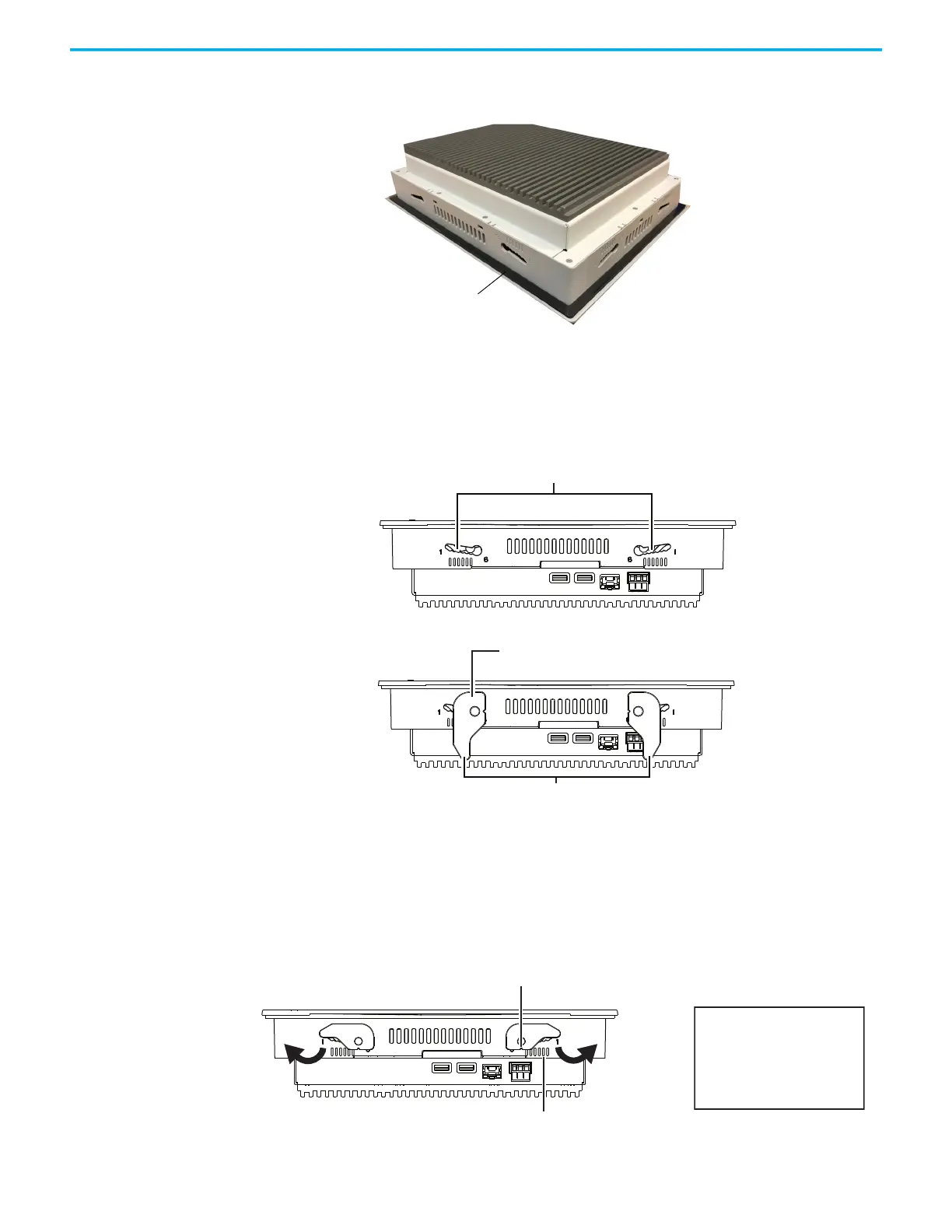
This gasket forms a compression type seal. Do not use sealing
compounds.
2. Place the integrated touch screen display in the panel opening.
3. Install all mounting levers in the mounting slots on the integrated touch
screen display.
Slide each level until the short, flat side of the lever touches the surface of
the panel.
4. When all levers are in place, slide each lever and additional notch or tow
until you hear a click.
5. Rotate each lever in the direction indicated until it is in the final latch
position.
Follow the latching sequence for the optimum fit.
Mounting slots
Short, flat side of mounting lever
Mounting levers
Rotate until notch in lever aligns with proper alignment mark.
Notch
Six alignment marks
1
3
8
5
4
2
7
6
Latching sequence
 Loading...


