128 Rockwell Automation Publication 750-IN100B-EN-P - July 2017
Chapter 5 Power Wiring
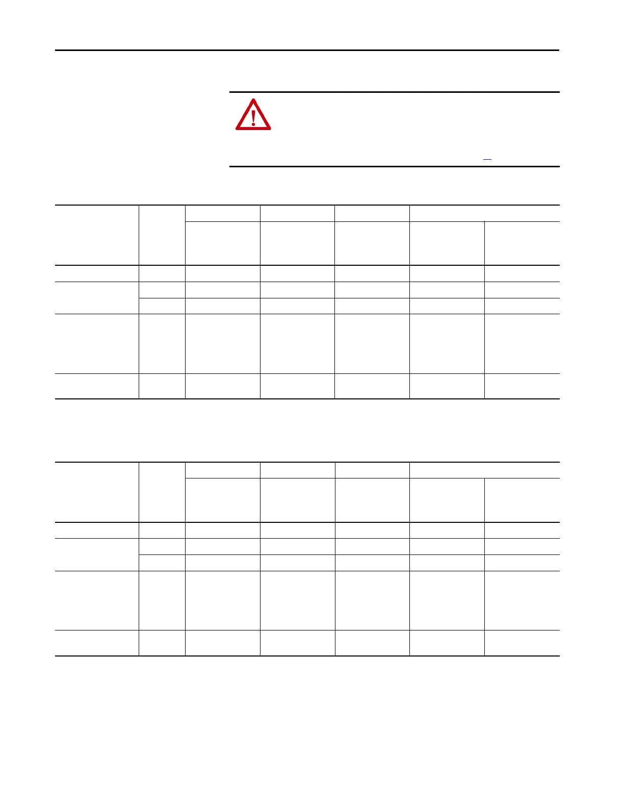
ATTENTION: Risk of equipment damage exists. The drive power source type
must be accurately determined. Jumpers PE-A, PE-A1, PE-A2, and PE-B1
must be configured for the power source type according to the
recommendations in the PowerFlex 755T Input Product RF Emission
Compliance and Installation Requirements table on page 30
.
Table 12 - PowerFlex 755TL/TR Drive Jumpers
Grounding Scheme EMC Option PE-A PE-A1 PE-A2 PE-B1
(MOV on the AC
Precharge Control
Circuit Board)
(MOV in the TVSS
Module)
(Common Mode Caps
on All AC Common
Mode Filter Circuit
Boards)
(Y-Caps on Line Side
Converter Power
Interface Circuit
Boards)
(Y-Caps on Motor
Side Inverter Power
Interface Circuit
Boards)
Factory Default C3 Connected (In) Connected (In) Connected (In) Disconnected (Out) Disconnected (Out)
Grounded C2
(2)
TBD TBD TBD TBD TBD
C3 Connected (In) Connected (In) Connected (In) Disconnected (Out) Disconnected (Out)
Ungrounded/High-
resistance Ground
(1)
AC fed ungrounded
Impedance grounded
B phase ground
N/A Disconnected (Out) Disconnected (Out) Disconnected (Out) Disconnected (Out) Disconnected (Out)
Marine Ungrounded /
High Resistance Ground
(1)
N/A Disconnected (Out) Disconnected (Out) Disconnected (Out) Disconnected (Out) Disconnected (Out)
(1) Ungrounded and high-resistance ground systems do not meet the EMC Directive due to the disconnected jumper positions.
(2) Rockwell Automation is evaluating the ability to meet Category C2 compliance. Contact the factory for more information.
Table 13 - PowerFlex 755TM Regenerative Bus Supplies Jumpers
Grounding Scheme EMC Option PE-A PE-A1 PE-A2 PE-B1
(MOV on the AC
Precharge Control
Circuit Board)
(MOV in the TVSS
Module)
(Common Mode Caps
on All AC Common
Mode Filter Circuit
Boards)
(Y-Caps on Line Side
Converter Power
Interface Circuit
Boards)
(Y-Caps on Motor
Side Inverter Power
Interface Circuit
Boards)
Factory Default C3 Connected (In) Connected (In) Connected (In) Disconnected (Out) N/A
Grounded C2
(2)
TBD TBD TBD TBD N/A
C3 Connected (In) Connected (In) Connected (In) Disconnected (Out) N/A
Ungrounded/High-
resistance Ground
(1)
AC fed ungrounded
Impedance grounded
B phase ground
N/A Disconnected (Out) Disconnected (Out) Disconnected (Out) Disconnected (Out) N/A
Marine Ungrounded /
High Resistance Ground
(1)
N/A Disconnected (Out) Disconnected (Out) Disconnected (Out) Disconnected (Out) N/A
(1) Ungrounded and high-resistance ground systems do not meet the EMC Directive due to the disconnected jumper positions.
(2) Rockwell Automation is evaluating the ability to meet Category C2 compliance. Contact the factory for more information.

 Loading...


