Rockwell Automation Publication 750-IN100B-EN-P - July 2017 33
Prepare for Installation Chapter 3
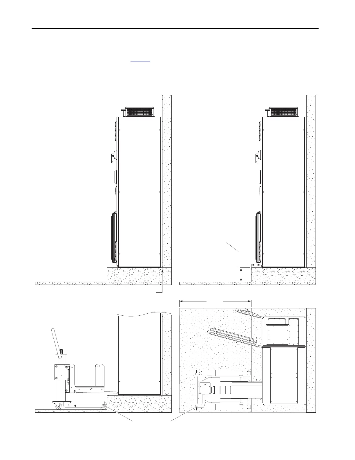
PowerFlex 755T products can be mounted on a service pad or platform. The
platform height and enclosure setback measurements that are indicated in
Figure 8
are the maximum that is allowed for by the PowerFlex 750-Series
service cart (20-750-MCART1). The platform height measurement is also an
installation limit per NEC requirements for the disconnect switch.
Figure 8 - Mounting Clearances for Enclosure Access
254 mm
(10 in.)
762 mm
(36 in.)
203 mm
(8 in.)
Side View
20-750-MCART1
Top View
Maximum Enclosure Setback
Maximum Platform or
Plinth System Height
Minimum Aisle WidthNo clearance is required between the back of the enclosure and a wall.
Side View
Side View

 Loading...


