80 Rockwell Automation Publication 750-IN100B-EN-P - July 2017
Chapter 4 Mechanical and Electrical Installation
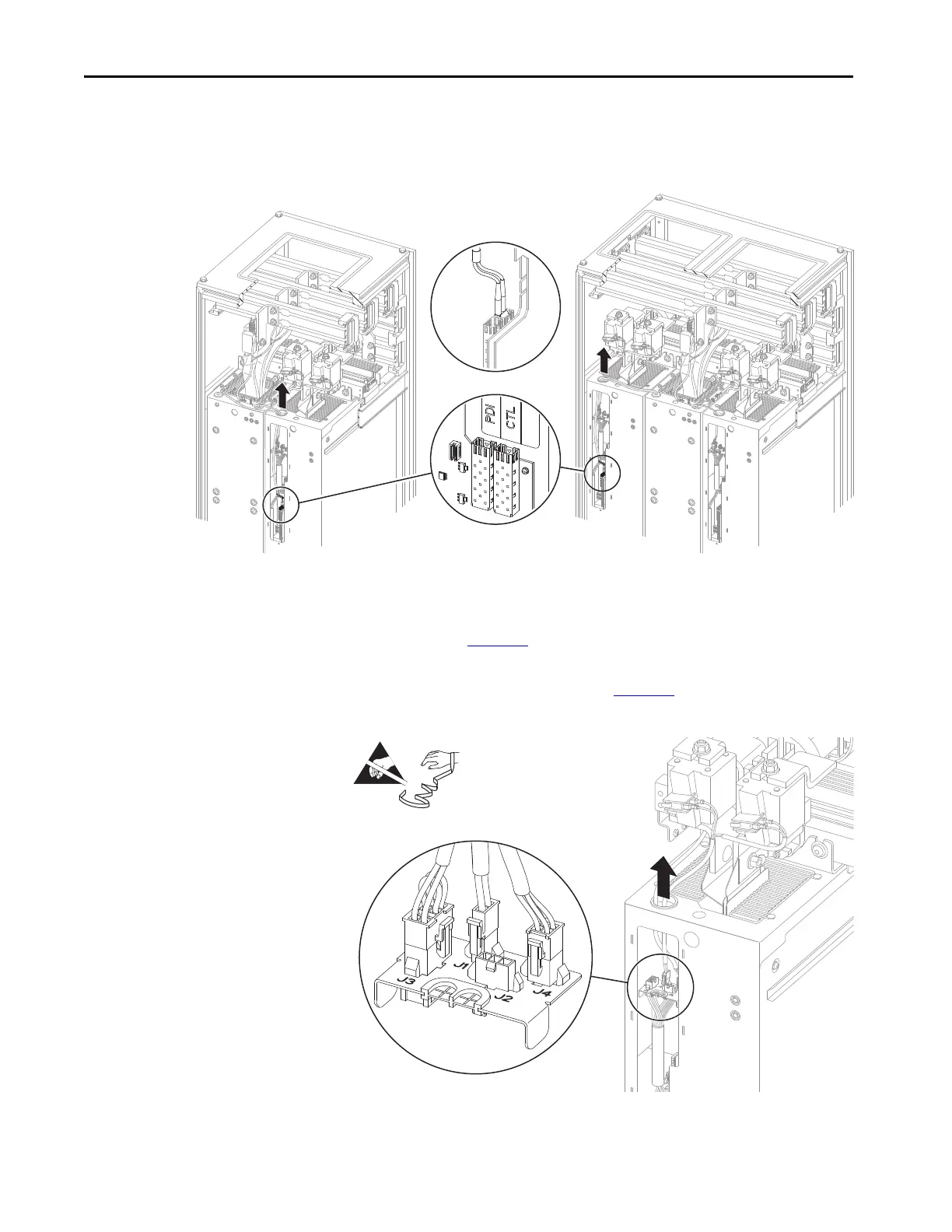
6. Disconnect the PDI and CTL fiber-optic cables, if present, from the
power layer interface circuit board.
Figure 42 - Power Module PDI and CTL Fiber-optic Cable Connections
7. Without bending the cable to a radius less than 50 mm (2 in.), carefully
remove the disconnected fiber-optic cables from the power module
chassis. See Figure 42
.
8. Disconnect any cables, P1 through P4, that are plugged into the I/O
panel in the power module(s). See Figure 43
.
Figure 43 - Power Module I/O Panel Connections
9. Carefully remove the disconnected cables from the power module
chassis.
LCL filter with one line side converter. LCL filter with two line side converters.

 Loading...


