82 Rockwell Automation Publication 750-IN100B-EN-P - July 2017
Chapter 4 Mechanical and Electrical Installation
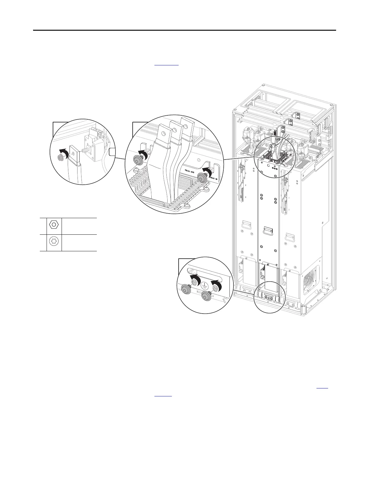
2. Remove the three M12 x 13 mm hex nuts that secure the flex bus cables
to the AC input fuse terminals and remove the flex bus cables. See
Figure 45
.
Figure 45 - Chassis and AC Bus Connections
3. Remove the two M10 x 20 mm screws that secure the LCL filter module
chassis to the control bus frame.
Leave the two M10 x 20 mm screws that secure the LCL filter module
chassis to the floor mounting bracket while preparing the PowerFlex
750-Series service cart.
4. Secure the service cart to the floor mounting bracket in the enclosure.
See PowerFlex 750-Series Service Cart Instructions, publication 750-
IN105, for information on using the service cart.
5. Remove the two remaining M10 screws to release the LCL filter
module.
6. Use the service cart, 20-750-MCART1, to remove the LCL filter
module from the enclosure.
1
M10
17 mm
38 N•m (336 lb•in)
2
M10 x 20mm
T45
42.4 N•m (375 lb•in)
Leave these M10 screws in
place while preparing the
service cart.
Step 14

 Loading...


