98 Rockwell Automation Publication 750-IN100B-EN-P - July 2017
Chapter 4 Mechanical and Electrical Installation
3. Connect the each fiber-optic cable to its designated CTL port on the
power module power layer interface circuit board. See Figure 38 on
page 74.
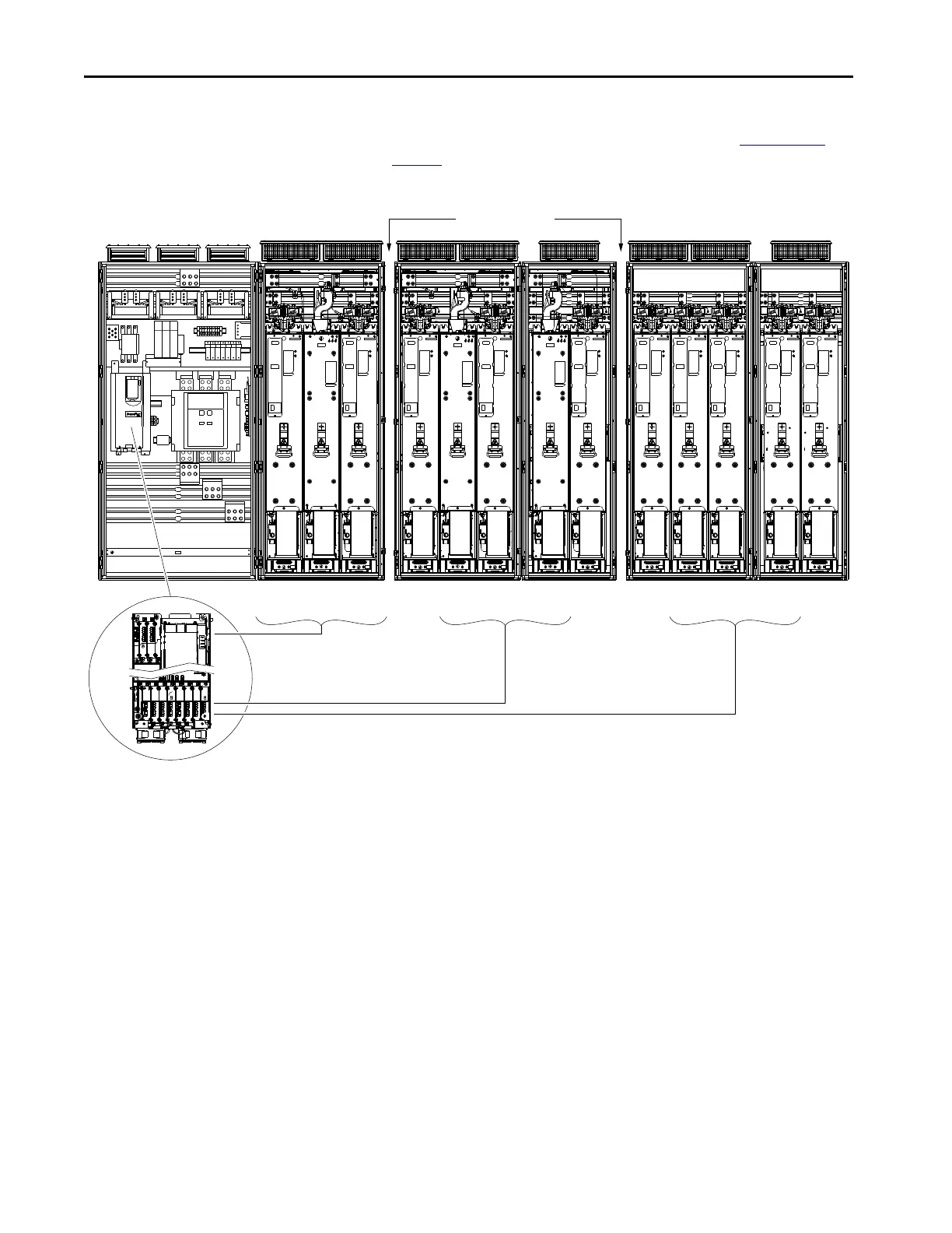
Figure 50 - Fiber Interface to CTL Port Connections
L0-CTL and L1-CTL connections
are made at the factory.
L2-CTL…L4-CTL Connections M0-CTL…M4-CTL Connections
Shipping Splits

 Loading...


