74 Rockwell Automation Publication 750-IN100B-EN-P - July 2017
Chapter 4 Mechanical and Electrical Installation
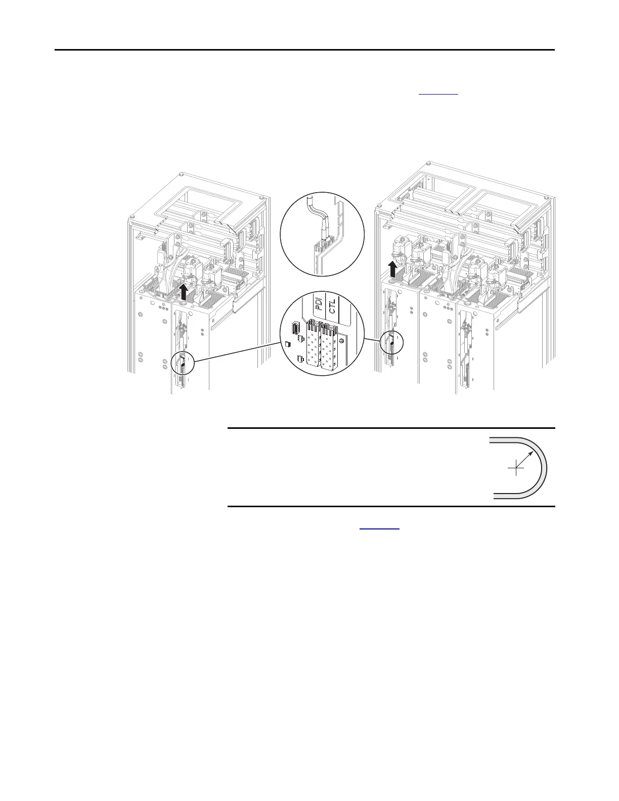
6. Disconnect the PDI and CTL fiber-optic cables, if present, from the
power layer interface circuit board. See Figure 38
.
7. Without bending the cables to a radius less than 50 mm (2 in.), carefully
remove the cables from the power module chassis.
Figure 38 - PDI and CTL Fiber-optic Cable Connections
For the following steps, refer to Figure 39.
8. If present, disconnect the cable connector P1 from connector J1 on the
I/O panel in the power module and remove the cable from the power
module chassis.
9. If present, disconnect the cable connector P2 from connector J2 on the
I/O panel in the power module remove the cable from the power
module chassis.
10. Disconnect the cable connector P3 from connector J3 on the I/O panel
in the power module and remove the cable from the power module
chassis.
11. Disconnect the cable connector P4 from connector J4 on the I/O panel
in the power module and remove the cable from the power module
chassis.
LCL filter with one line side converter LCL filter with two line side converters
IMPORTANT
Minimum inside bend radius for fiber-optic cable is 50
mm (2 in.). Any bends with a shorter inside radius can
permanently damage the fiber-optic cable. Signal
attenuation increases as inside bend radius is
decreased.
 Loading...


