EasyManuals Logo
Home>Allen-Bradley>Adapter>PowerFlex 755T

Allen-Bradley PowerFlex 755T Installation Instructions

Allen-Bradley PowerFlex 755T
192 pages
To Next Page IconTo Next Page
To Previous Page IconTo Previous Page
Page #75 background imageLoading...
Page #75 background image
Rockwell Automation Publication 750-IN100B-EN-P - July 2017 75
Mechanical and Electrical Installation Chapter 4
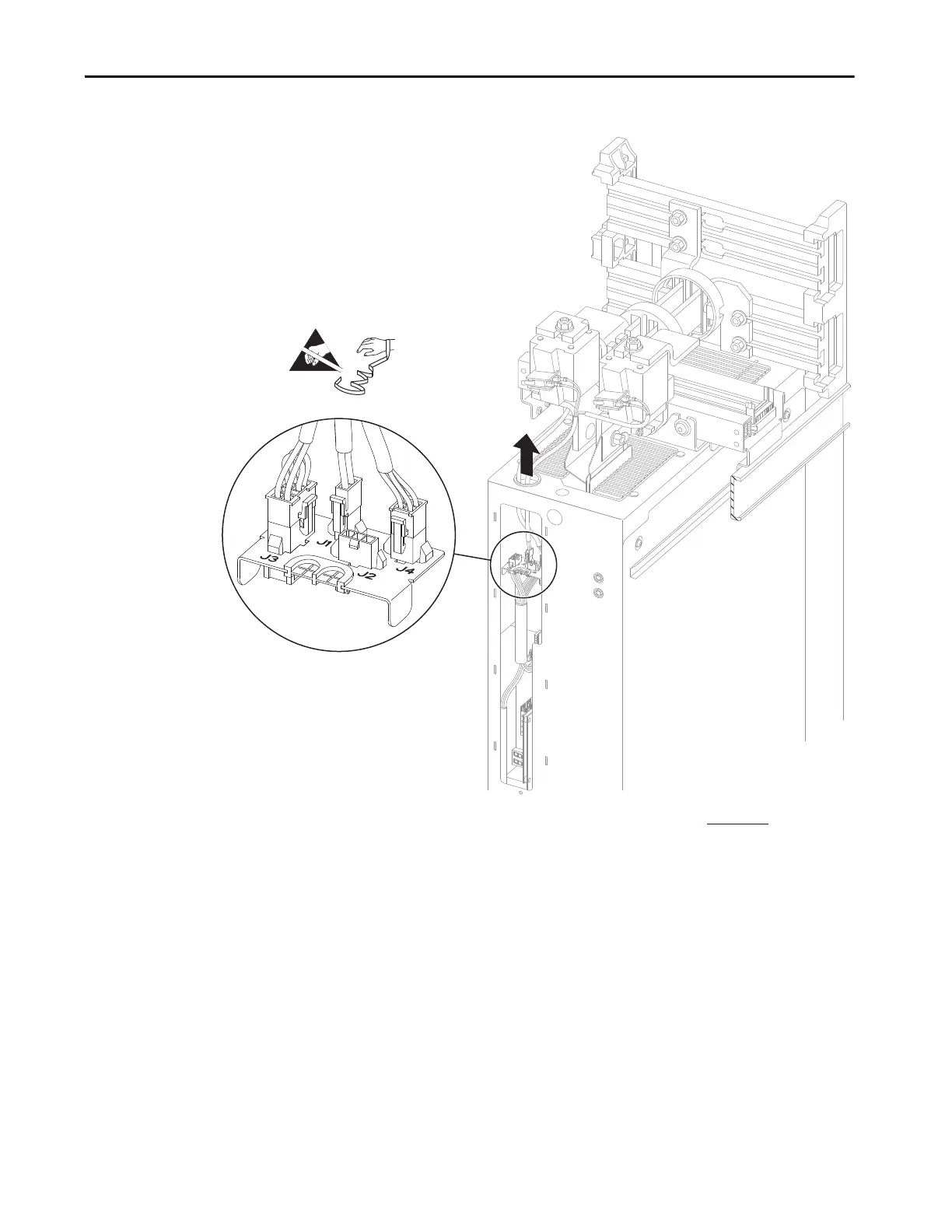
Figure 39 - Power Module I/O Panel Connections
12. Loosen the two M10 x 10 mm hex nuts (See 1 in Figure 40) that secure
the power input/output terminals to the DC precharge module or DC
link fuse terminals. It is not necessary to remove these hex nuts.
A ratcheting wrench is recommended to help access these hex nuts.
P1
P4
P3
=

Table of Contents

Other manuals for Allen-Bradley PowerFlex 755T

Questions and Answers:

Question and Answer IconNeed help?

Do you have a question about the Allen-Bradley PowerFlex 755T and is the answer not in the manual?

Allen-Bradley PowerFlex 755T Specifications

General IconGeneral
BrandAllen-Bradley
ModelPowerFlex 755T
CategoryAdapter
LanguageEnglish

Related product manuals